Model
280B
ILLUSTRATIONS
Page
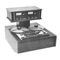
1-1 Professional
Recorder/Reproducer
Series
280B
. . . . . . .
..
1-1
1-2
Remote
Control
Unit
Accessory. . . . . . . . . . . . . . . . . . .
..
1-5
2-1
Mounting
Dimensions
..
...
.......................
2-2
2-2
Interconnection
Diagram.
. . . . . . . . . . . . . . . . . . . . . . .
..
2-4
2-3
Power
Supply
Jumper
. . . . . . . . . . . . . . . . . . . . . . . . . .
..
2-5
3-1
Controls
and
Indicators.
. . . . . . . . . . . . . . . . . . . . . . . .
..
3-2
3-2
Tape
Threading
Path
. . . . . . . . . . . . . . . . . . . . . . . . . . .
..
3-3
6-1
System
Block
Diagram.
. . . . . . . . . . . . . . . . . . . . . . . . .
..
6-2
6-2
Transport,
Bottom
View. . . . . . . . . . . . . . . . . . . . . . . . .
..
6-3
7-1
Brake
Adjustments
.....
.
.........................
7-2
7
-2
Suggested
Method
of
Adjusting
Brake
Torque.
. . . . . . .
..
7-3
7
-3
Head
Adjustment.
. . . . . . . . . . . . . . . . . . . . . . . . . . . . .
..
7-4
7-4
Motion
Sense
Adjustment
.
.....
..
. .
...............
7-5
7-5
Tension
Post
Adjustments
..
.......................
7-6
7-6
Pinch
Roller
Adjustment.
. . . . . . . . . . . . . . . . . . . . . . .
..
7-6
7-7
Power
Supply.
. . . . . . . . . . . . . . . . . . . . . . . . . . . . . . . .
..
7-7
7
-8
Constant
Tension
Adjustment
Procedures.
. . . . . . . . . .
..
7-8
7
-9
Constant
Tension
Assembly
.......................
, 7-9
7-10
ATL
Adjustment
.....
..
.........................
7-9
7-11
Initial
Test
Setup
.........
.
......................
7-10
7-12
Electronics
Assembly,
Top
View.
. . . . . . . . . . . . . . . . .
..
7-11
7-13
Equalization
PWA
Adjustments.
. . . . . . . . . . . . . . . . . .
..
7-12
7-14
Record/Playback
Amplifier
PWA
Adjustment
and
Test
Points.
. . . . . . . . . . . . . . . . . . . . . . . . . . . . .
..
7-13
7-15
Regulator,
Bias
Oscillator
and
Amplifier
PWA
..........
7-14
7-16
Bias
Amplifier
PWA
Adjustment
and
Test
Points
..
.
...
" 7-
15
8-1
Transport
Logic,
Schematic
Diagram·
. . . . . . . . . . . . . .
..
8-3
8-2
Regulator,
Bias
Oscillator
and
Amplifier
PW
A
.........
8-5
8-3 Bias
Amplifier
PW
A,
Schematic
Diagram.
. . . . . . . . . . .
..
8-7
8-4
Record/Playback
Amplifier
PWA,
Schematic
Diagram.
.
..
8-9
8-5
Record/Playback
Equalization
PWA
.................
8-11
8-6
Motherboard
PWA
Schematic
Diagram
...............
8-13
8-7
Primary
Power
Supply,
Schematic
Diagram
...........
8-15
8-8 Relay
Control
Chassis
Interconnect
.................
8-17
8-9 Erase
Head
Matching
Board
Schematic
Diagram
........
8-19
8-10
Motion
Direction
Sensor
PWA
.....................
8-21
8-11
Squelch
PWA
............
.
.....................
8-21
8-12
Remote
Control
..................
. .
...
.........
8-22
8-13
Line
Amplifier
PWA
Monitor
and
Speaker
Assembly
....
8-23
8-15
Transport
Assembly (1
of
2) . . . . . . . . . . . . . . . . . . . . .
..
8-31
v
 Loading...