E-6
System preparation
764 mm
Wall mounting
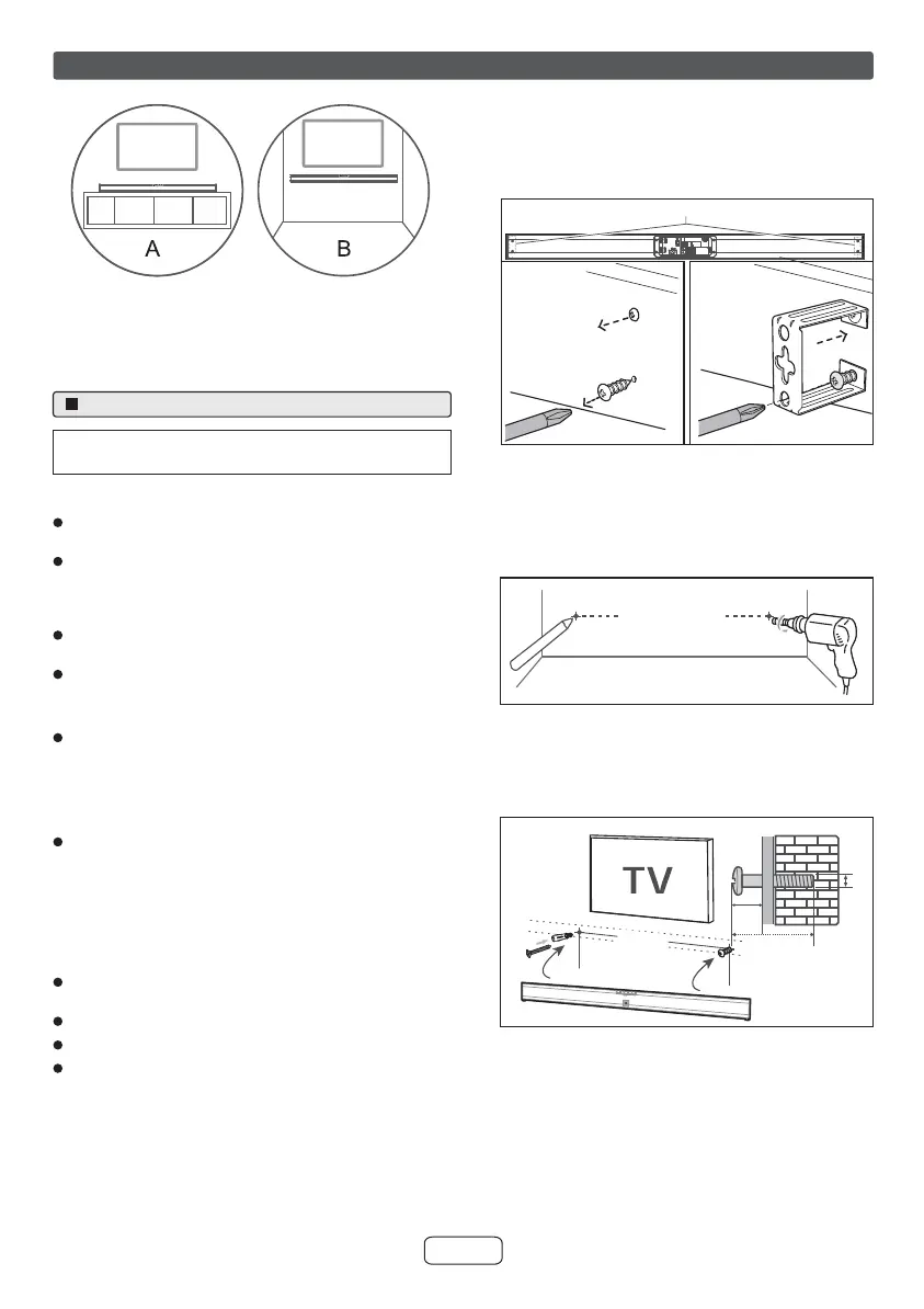
A: Normal Placement (place Sound bar on levelled surface
in front of TV)
B: Wall Mounting
Notes:
Installation must be carried out by qualified personnel
only. Incorrect assembly can result in severe personal
injury and property damage (if you intend to install this
product yourself, you must check for installations such
as electrical wiring and plumbing that may be buried
inside the wall). It is the installer’s responsibility to verify
that the wall will safely support the total load of the
sound bar and wall brackets.
Additional tools (not included) are required for the
installation.
Do not overtighten screws.
Keep this instruction manual for future reference.
Use an electronic stud finder to check the wall type
before drilling and mounting.
Cautions:
Be very careful to prevent the sound bar [1.3 kg
(2.9 lbs.) ] from falling when mounting on the wall.
Before mounting, check the wall strength. (Do not put
on the veneer plaster or whitewashed wall. The sound
bar may fall.) If unsure, consult a qualified service
technician.
Mounting screws are not supplied. Use appropriate
ones.
Check all wall mount angle screws for looseness.
Select a good location. If not, accidents may occur or
the sound bar may get damaged.
SHARP is not responsible for accidents resulting
from improper installation.
Make sure to unplug the AC power lead before
installing the sound bar or changing the position.
Remove the rear screws from the sound bar.
Attach the wall brackets to the sound bar with the
screws removed from it.
1
2
Drill 2 parallel holes (Ø 4mm - 8mm each according to
wall type) in the wall. The distance between the holes
should be 764 mm. Firmly fix 1 dowel into each hole in
the wall if necessary.
Leave a 5mm gap between the wall and the screw’s
head. Lift the sound bar with the attached wall brackets
over the heads of the screws and slot into place.
3
4
12
> 32mm
(5 mm)
4 mm
764 mm
764mm
 Loading...