EasyManua.ls Logo

Sharp LC-32LE511E User Manual

Sharp LC-32LE511E
156 pages
To Next Page IconTo Next Page
To Previous Page IconTo Previous Page
Page #12 background image
12
LC-32LE511
LC-40LE511
LC-40LE531
Operation Manual (Continued)
English - 12 -
PC/YPbPr Audio Inputs4. are used for connecting audio signals of a PC or a device that connects to the
TV via YPbPr. Connect the PC audio cable between the AUDIO INPUTS on the TV and audio output
of your PC to enable PC audio. Connect the audio cable between AUDIO INPUTS on the TV and audio
outputs of your device to enable component audio.
Subwoofer Out5. is for connecting an external, active subwoofer to the set to give a much deeper bass
effect. Use an appropriate RCA cable to connect the set to a subwoofer unit.
S/PDIF Digital Out6. outputs digital audio signals of the currently watched source.
Use a digital optic cable to transfer audio signals to a device that has S/PDIF input.
RF Input7. connects to an aerial or cable system.
Note that if you use a decoder or a media recorder, you should connect the aerial cable through the
device to the television with an appropriate antenna cable, as shown in the illustration in the following
pages.
HDMI 3: HDMI Input8.
HDMI 2: HDMI Input9.
HDMI 1: HDMI Input10.
HDMI Inputs are for connecting a device that has an HDMI socket. Your LCD TV is capable of
displaying High De nition pictures from devices such as a High De nition Satellite Receiver or DVD
Player. These devices must be connected via the HDMI sockets or Component Socket. These sockets
can accept either 720p or 1080p (optional) signals. No sound connection is needed for an HDMI to
HDMI connection.
PC Input11. is for connecting a personal computer to the TV set.
Connect the PC cable between the PC INPUT on the TV and the PC output on your PC
Ethernet input (for service).12.
Viewing the Connections - Side Connectors
CI Slot is used for inserting a CI card. A CI card allows you to view all the channels that you subscribe 1.
to. For more information, see “Conditional Access” section.
USB Inputs. 2.
Note that programme recording feature is available via these USB inputs. You can connect external
hard disk drives to this input.
Side HDMI Input (HDMI 4) is for connecting a device that has an HDMI socket.3.
Headphone jack is used for connecting an external headphone to the system. Connect 4.
to the HEADPHONE jack to listen to the TV from headphones (optional).
Side audio-video connection5. input is used for connecting video and audio signals
of external devices. To make a video connection, you must use the supplied AV
connection cable for enabling connection. First, plug singular jack of the cable to the
TV’s Side AV socket. Afterwards, insert your video cable’s (not supplied) connector into
the YELLOW input (located on the plural side) of the supplied AV connection cable.
Colours of the connected jacks should match.
To enable audio connection, you must use RED and WHITE inputs of the side AV
connection cable. Afterwards, insert your device’s audio cable’s connectors into
the RED and WHITE jack of the supplied side AV connection cable. Colours of the
connected jacks should match.
Note: You should use audio inputs of side AV connection cable (RED & WHITE)
to enable sound connection when connecting a device to your TV by using PC or
COMPONENT VIDEO input.
[GB]_MB70_1910UK_IDTV_T2_32942LED_STORE_MODE_GOLD11_10072643_50186875.indd 12 06.07.2011 15:28:50
Question and Answer IconNeed help?

Do you have a question about the Sharp LC-32LE511E and is the answer not in the manual?

Sharp LC-32LE511E Specifications

General IconGeneral
BrandSharp
ModelLC-32LE511E
CategoryLED TV
LanguageEnglish

Summary

Service Manual Overview

Electrical Specifications

Important Service Safety Precautions

Warning and Fire/Shock Hazard Notes

Crucial warnings regarding modifications and handling of electrical hazards.

Safety Checks and Leakage Current Test

Procedures for ensuring safety before returning the unit, including leakage current testing.

Operation Manual

Remote Control Buttons Overview

Identifies and describes the functions of each button on the remote control handset.

Circuit Descriptions

Audio Amplifier Stages

Details the main audio amplifier (TPA3110) for audio output, including its general description and features.

Power Stage

MB70 Power Management Block Diagram

Illustrates the power management architecture and the role of the 17PW26 power board.

Microcontroller (Broadcom)

BCM3556 General Description and Features

Details the BCM3556 SoC, its integration of DTV functions, and advanced multimedia capabilities.

Video Back-End Processor (Trident)

PNX5120EH General Description and Features

Explains the PNX5120EH video improvement IC, its picture processing features, and technical specifications.

FPGA (Spartan-3E)

USB Interface

USB Circuit Components and Function

Explains the USB interface connectivity and its main components, including protection ICs.

DVB-C/T2 Demodulator

Sony CXD2820R Key Features

Details the Sony CXD2820R demodulator, its standards compliance, and supported modes.

Low Power&CEC Microcontroller

HDMI Switch

Silicon Image SiI9287B Key Features

Outlines the key features of the SiI9287B HDMI switch, including its processing capabilities and compliance.

Software Update

Main SW Update Procedure

Instructions for updating the main IC software via USB ports.

Panel Configuration File Update

Steps for updating the panel configuration file using USB for new panel settings.

Stby-Microcontroller File Update

Procedure to update the standby microcontroller firmware via the service menu.

Troubleshooting

No Backlight Problem Diagnosis

Guides on diagnosing and resolving issues related to the absence of backlight on the TV panel.

CI Module Problem Diagnosis

Troubleshooting steps for CI module issues, focusing on supply, control pins, and mechanical checks.

Staying in Stand-by Mode

Addresses issues where the TV remains in standby mode without other operations, suggesting Vcc short checks.

IR Problem Diagnosis

Troubleshooting steps for IR or LED functionality issues, checking the LED card supply.

Keypad Touchpad Problems

Guidance on diagnosing and resolving issues with the keypad or touchpad not functioning.

USB Problems and No Sound

Troubleshooting for USB detection issues and lack of audio output, checking supply voltages.

Standby On/Off Problem Diagnosis

Addresses TV boot issues or hangs in standby mode, suggesting power supply and SW checks.

No Signal Problem Diagnosis

Troubleshooting steps for missing TV signals, checking tuner settings and AGC voltage.

Service Menu Settings

Accessing and Navigating Service Menu

Instructions on how to access the service menu using the remote control and its main screen.

Schematic Diagrams

HDMI, USB, Ethernet & Keyboard Schematics

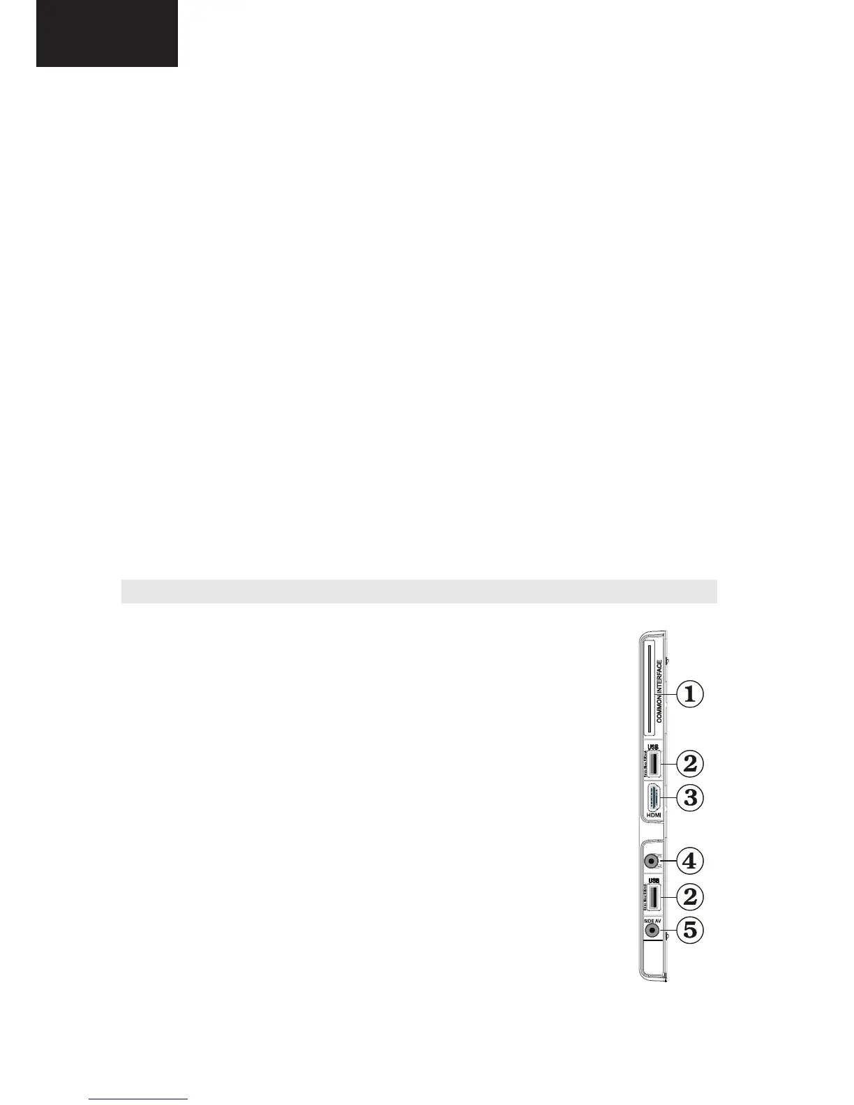
Provides detailed circuit diagrams for the HDMI, USB, Ethernet, and Keyboard interfaces.

Power Supply Diagram

Halft-Bridge Resonant Mode Power Supply

Detailed schematic of the half-bridge resonant mode power supply unit.

Replacement Parts Listing

Related product manuals