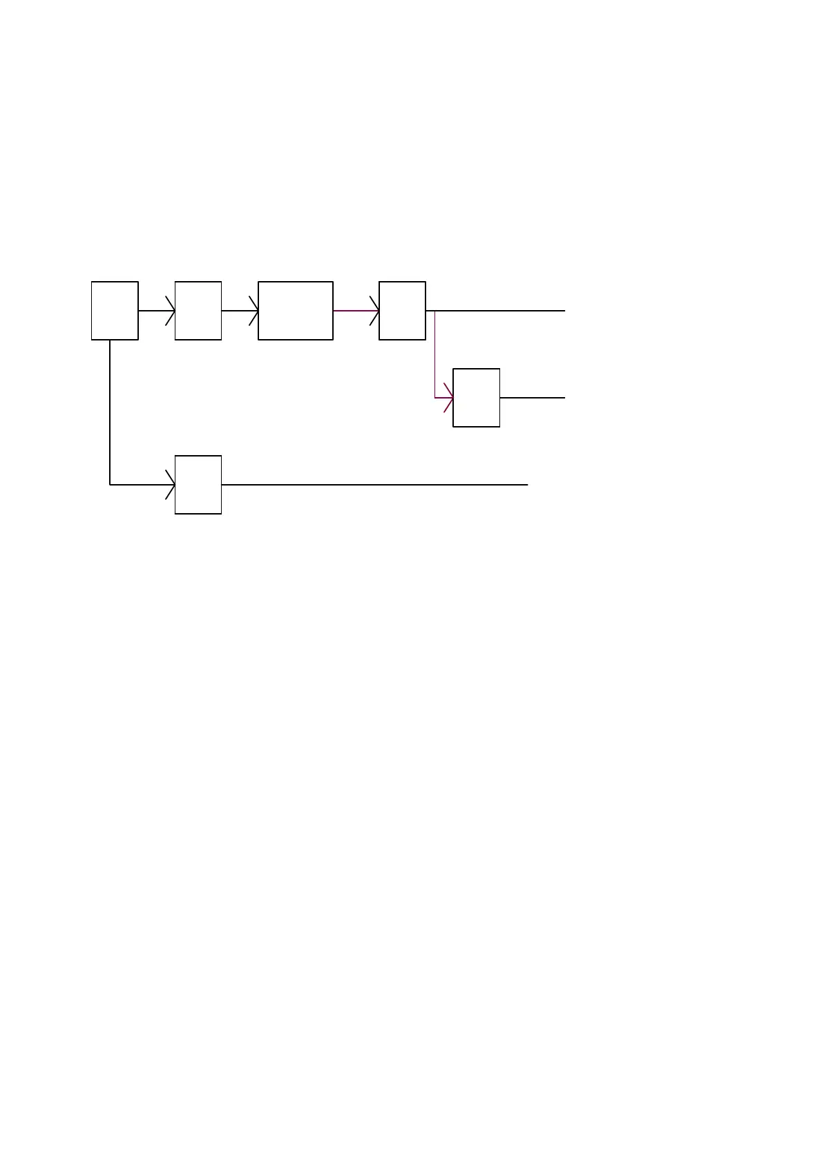
[2]POWER MANAGEMENT BLOCK DIAGRAM
There are 1 part circuits in Power board of this project (fig.1), Power circuits which is a single layer board,
There are 3 output in the power parts, one is interface board including USB and TV tuner et; the other is
inverter board and audio circuit.+24V output is inverter part. The system block diagram as below; the last
is panel Vcc and audio, the power is 12V.
DC:24V/1.6A output to Inverter
Standby
DC:5.3V/2A output to IF BD
DC-DC
Rectifier
filter
ACD
DC:12V/2.23A output to
Audio
AC
INPUT
EMI
ACD
(fig.1)
 Loading...