LC-42/46/52D64U
6 – 1
LC-42/46/52D64U
Service Manual
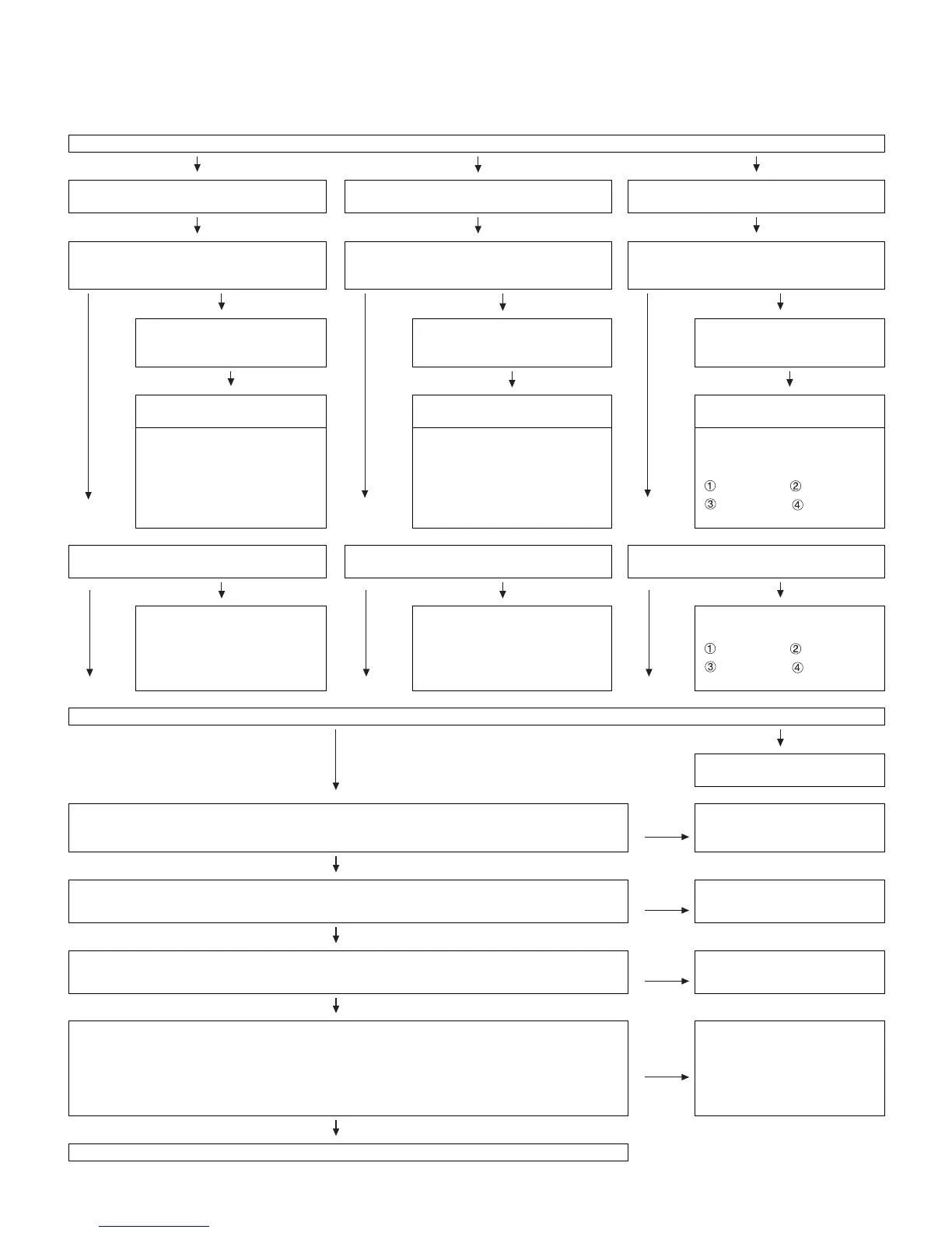
CHAPTER 6. TROUBLE SHOOTING TABLE
[1] TROUBLE SHOOTING TABLE
No video (1)
COMPOSITE: No external input video
[INPUT-1]
COMPOSITE: No external input video
[INPUT-2]
COMPOSITE: No external input video
[INPUT-3]
Is INPUT-1 selected on the input select
menu screen? Is the INPUT-SELECT for the
input signal?
Is INPUT-2 selected on the input select menu
screen?
Is INPUT-3 selected on the input select
menu screen?
YES
NO
YES
NO
YES
NO
Select INPUT-1 on the input
select menu screen for the right
input signal.
Select INPUT-2 on the input
select menu screen.
Select INPUT-3 on the input
select menu screen.
Does the INPUT-1 V3_PLUG
detection function?
Does the INPUT-2 V2_PLUG
detection function?
Does the INPUT-3 V1_PLUG
detection function?
Check the line between pin (7)
of input terminal (J501) and pin
(37) of IC501 (AV_SWITCH).
Check the line between pin (7) of
input terminal (J503) and pin (35)
of IC501 (AV_SWITCH).
Check the line between pin (7)
of input terminal (J901) and pin
(33) of IC501 (AV_SWITCH).
J901 pin (7) P901 pin (7)
P501 pin (7) IC501 pin
(33)
Is there the COMPOSITE video signal input
at pin (38) of IC501 (AV_SWITCH)?
Is there the COMPOSITE video signal input at
pin (36) of IC501 (AV_SWITCH)?
Is there the COMPOSITE Video signal input
at pin (34) of IC501 (AV_SWITCH)?
YES
NO
YES
NO
YES
NO
Check the line between pin (6)
of J501 and pin (38) of IC501.
Check the line between pin (6) of
J503 and pin (36) of IC501.
Check the line between pin (6)
of J901 and pin (34) of IC501.
J901 pin (6) P901 pin (5)
P501 pin (5) IC501 pin
(34)
Is there the COMPOSITE video signal output at pin (30) of IC501?
YES
NO
Check IC501 and its peripheral
circuits.
Is there the COMPOSITE video signal output at pin (59) of connector (SC501) on the TERMINAL
unit?
NO
Check the line between IC501
and SC501 (Q501 and Q502,
etc.).
YES
Is there the COMPOSITE video signal input at pin (59) of connector (SC2203) on the MAIN unit? NO Check the SC501 and SC2203
connectors.
YES
Is there the COMPOSITE video signal input at pin (AN16) of IC8001 (CPU)? NO Check the line between SC2203
and IC8001 (Q2216, etc.).
YES
Are the LVDS signal outputs at the LVDS 1st channel and 2nd channel of IC8001?
LVDS_TX_0_DATA0_P/N(C7/B7), LVDS_TX_0_DATA1_P/N(E7/D7), LVDS_TX_0_DATA2_P/N(C6/
B6), LVDS_TX_0_DATA3_P/N(C5/B5), LVDS_TX_0_DATA4_P/N(E5/D5), LVDS_TX_0_CLK_P/
N(E6/D6), LVDS_TX_1_DATA0_P/N(B4/A4), LVDS_TX_1_DATA1_P/N(E4/D4),
LVDS_TX_1_DATA2_P/N(B3/A3), LVDS_TX_1_DATA3_P/N(B1/B2), LVDS_TX_1_DATA4_P/N(F5/
F6), LVDS_TX_1_CLK_P/N(C2/C3).
NO
Check IC8001 and its peripheral
circuits (IC8151 thru IC8154,
etc.).
YES
Check the panel module.