LC-60/70LE650U/C6500U/LE657U,LC-60/70LE755U/LE757U/LE857U/C7500U
5 – 11
8.2. Image adjustment
8.2.1 Device check
Before adjustment, check that the adjustment jig and signal source are set for Sharp LCD US.
Signal generator level adjustment check (Adjust to the standard value level.)
8.2.2 Process mode
8.2.3 Composite N358 signal/tuner adjustment
• Composite signal: 0.714Vp-p ± 0.02Vp-p (Pedestal to white)
• 15K component signal: Y level: 0.714Vp-p± 0.02Vp-p (Pedestal to white)
PB/PR level: 0.7Vp-p ± 0.02Vp-p
• 33K component signal: Y level: 0.7Vp-p ± 0.02Vp-p (Pedestal to white)
PB/PR level: 0.7Vp-p ± 0.02Vp-p
• Analog RGB: RGB level: 0.7Vp-p ± 0.02Vp-p (Pedestal to white)
Adjustment point Adjustment conditions Adjustment procedure
Process mode Enter the process adjustment mode using the process adjustment remote control.
Adjustment point Adjustment conditions Adjustment procedure
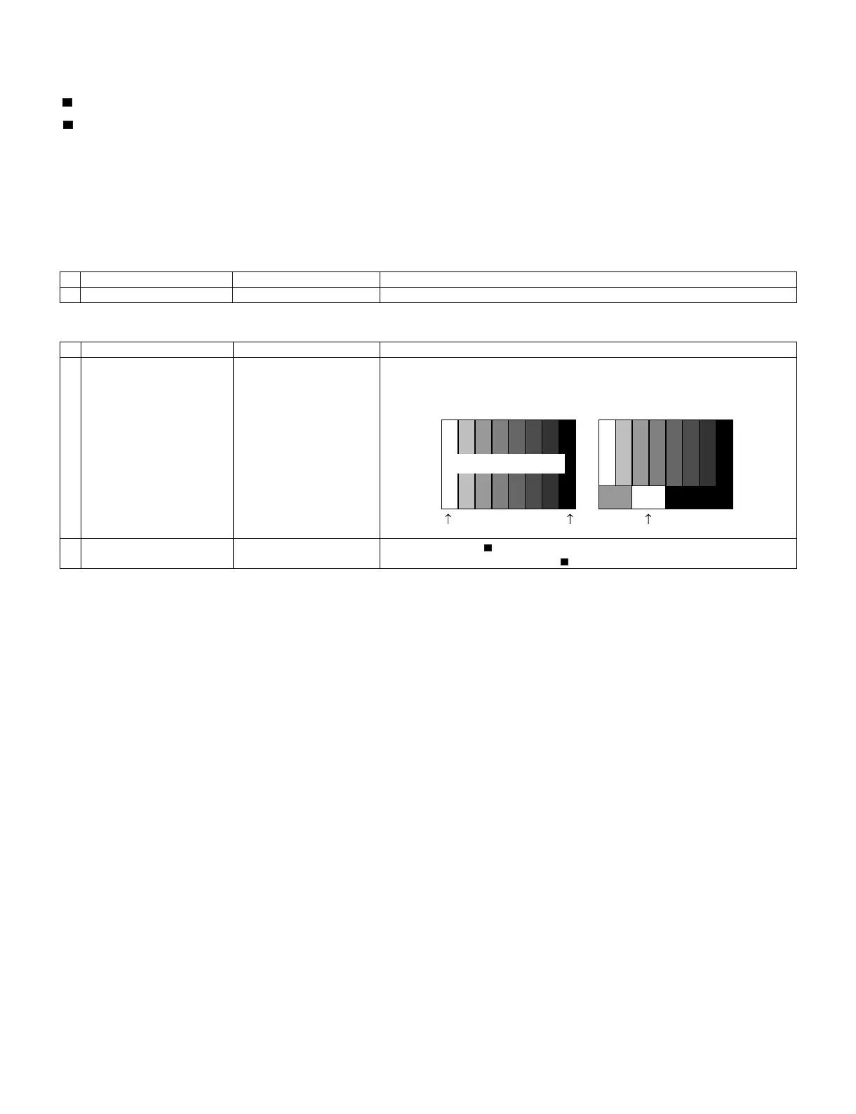
1 Setting N358 signal
US-10ch
• Send the N358 color bar (color saturation: 75%) signal to the composite input.
• Send the in-house signal (use US-10ch) to TUNER.
2 Automatic adjustment exe-
cution
Point the cursor to [ N358 ALL ADJ(INPUT2)] and press the [Enter] key.
The adjustment is complete when [ N358 ALL ADJ(INPUT2) OK] is displayed.
[Video input signal] [In-house US-10ch]
100% white 100% white
0% black
Color saturation: 75%
 Loading...