11
T242 Trimmer
Assembly
The unit should now be completely assembled and ready for use.
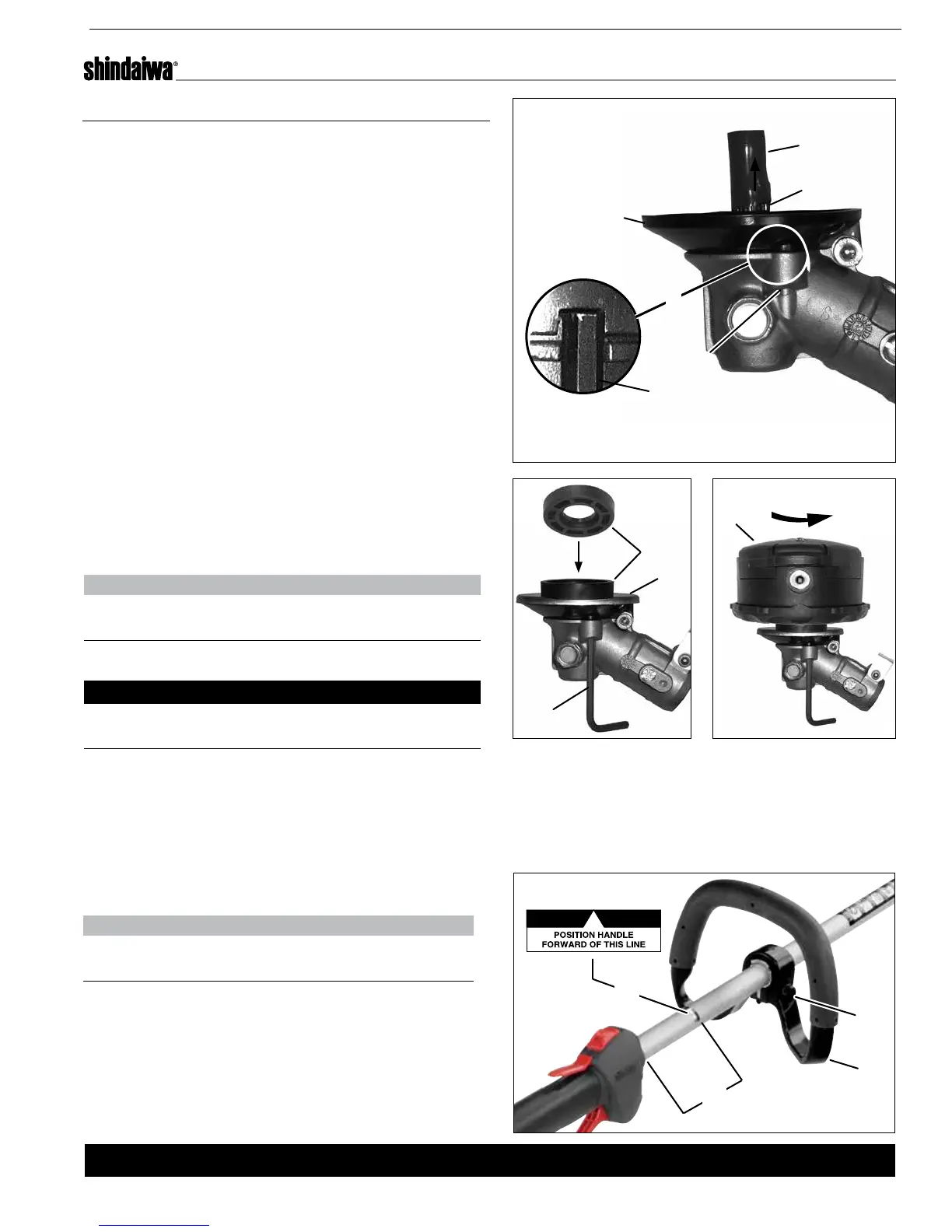
1. Turn the trimmer over so that the gear case
output shaft (A) faces UP.
2. Remove and discard the plastic tube (B) from the
output shaft (A).
3. Lock gear case by inserting a 4mm hex wrench
(C) into locking hole (D).
4. Apply light force to wrench (C) while turning
output shaft (A).
5. Continue turning until wrench (C) engages locking
notch (E) on underside of holder (F).
6. Hold wrench (C) securely to prevent output shaft
(A) from turning.
7. Install xing plate (H) onto holder.
8. Place nylon spacer (G) on xing plate (H). Match
small (25 mm) diameter recess in nylon spacer
(G) to mounting arbor on xing plate (H).
9. Assemble trimmer head (J) to output shaft (A),
turning trimmer head counterclockwise. Tighten
trimmer head securely, using hand pressure only.
NOTE:
Nylon spacer (G) must stay centered on mounting
arbor during tightening.
10. Remove wrench (C).
IMPORTANT!
The trimmer head has a left-hand thread. For
removal turn the trimmer head clockwise.
To Advance Trimmer Line
To advance trimmer line, tap trimmer head (J)
against the ground while the head is turning at
normal operating speed.
Assembly
Install the Speed-Feed
©
Trimmer Head
Position the Support Handle
NOTE:
Label (A) shows minimum spacing (B) for the
support handle location.
1. Position support handle (C) for comfortable
operation and secure screw (D).
D
C
B
A
A
F
G
J
B
C
D
E
H
C

 Loading...