Shure LX4 Diversity Receiver
18
Service Procedures
25D1008 (BK)
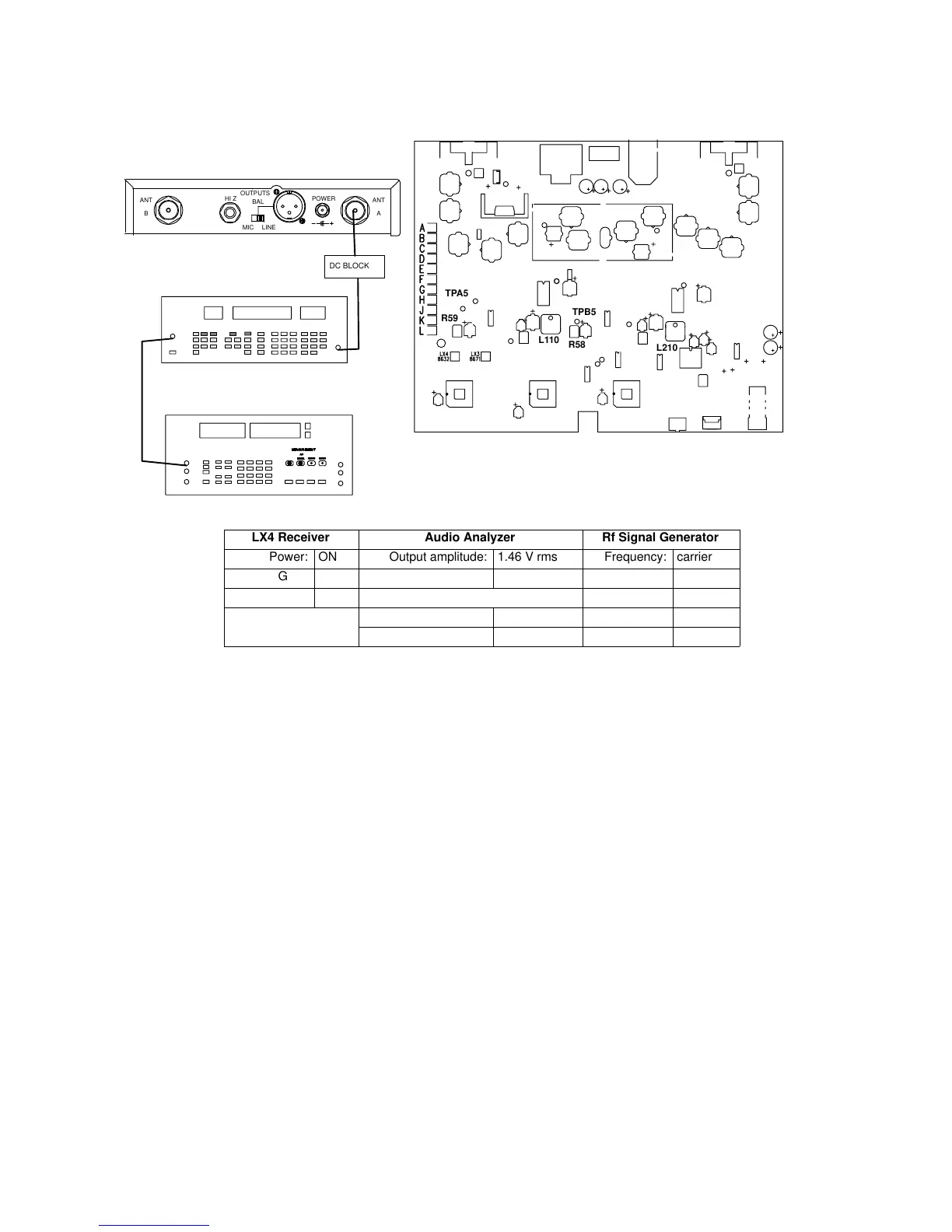
Audio Level Adjustments
RF SIGNAL GENERATOR
NOTE: DC VOLTAGES ARE PRESENT AT MOST
RF TEST POINTS. USE A DC BLOCK ON THE
RF SIGNAL GENERATOR TO PROTECT
TEST EQUIPMENT.
AUDIO ANALYZER
12.5 – 18.9 VDC
ANTANT
OUTPUTS
HI Z
BAL
MIC LINE
POWER
AB
L110
L210
R58
TPB5
TPA5
R59
DC BLOCK
LX4 Receiver Audio Analyzer Rf Signal Generator
Power: ON Output amplitude: 1.46 V rms Frequency: carrier
Gain: Max Frequency: 1 kHz Modulation: FM
Squelch: Mid Filters: Mod source: EXT
400 Hz High-Pass: ON Amplitude: –60 dBm
30 kHz Low-Pass: ON Deviation: 15 kHz
Figure 5. Audio Level Adjustments Test Setup
Note: Remove the 33KΩ resistor from test point TPA4 and TPB4.
Note: The amplitude may have to be adjusted so that neither the HI EXT nor the LO EXT LEDs
on the rf signal generator are on. This amplitude should be between 1.4 and 1.5 V rms.
Note: Place a jumper between TPB7 and ground to mute channel B for channel A alignment.
(Place a jumper between TPA7 and ground to mute channel A for channel B alignment.)
1. Set the rf signal generator frequency to the same as the LX4, its
modulation to FM, its modulation source to EXT, its FM deviation
to 15 kHz, and its amplitude to –60 dBm.
2. Set the audio analyzer’s audio frequency to 1 kHz and its
amplitude to 1.46 V rms.
3. Connect the output of the audio analyzer to the input of the
rf signal generator.
4. Place a probe on TPA5, U1, pin 1 (TPB5) and adjust
L110 (L210) for maximum ac voltage.
5. With the probe still on TPA5 (TPB5), adjust R59 (R58) for
0.775 V ± 50 mV rms (1 kHz tone).
Repeat this test for channel B.
 Loading...