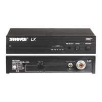
Shure LX4 Diversity Receiver
Characteristics325D1008 (BK)
Diversity Control Signals
The dc noise signals are compared by U3A, U3B, U3C, and U3D to
produce diversity control signals. These signals directly control analog
switches U6A and U6B, and diversity A/B LEDs D9 and D10. These
switches control the flow of audio signals from U1A and U2A.
Squelch Control
Squelch comparators U3A and U3C compare a dc level from the
user squelch control, R66, to the dc noise level signals coming from each
diversity channel. When the noise level in both channels exceeds a pre-
set level, the audio output of the receiver is squelched. Comparator
U4A provides additional signal attenuation in the squelched state by
shutting off compander U9B.
However, if the noise level in each channel is comparable and below
the squelch threshold, then U3B and U3D will allow both channels to be
active and both diversity indicators will be illuminated. Because the
signals from each channel are correlated, but the noise is uncorrelated,
a theoretical signal-to-noise improvement of 3 dB is possible with this
arrangement.
Balanced LO-Z Output
After passing through analog switches U6A and U6B, audio signals
from the two channels are buffered by U5A before entering three-pole,
low-pass filter Q1. They then enter compander U9B, which provides 2:1
logarithmic expansion. An additional IC amplifier U5B operates in con-
junction with U9B to provide a lower noise floor. The output of this stage
is applied to volume level control R32. In order to provide a balanced
LO-Z output, U5C and U5D operate as a bridging amplifier. HI-Z audio
output connector J3 taps off U5D output.
Audio Indicators
An audio LED indicator display lets the user know when the transmit-
ter (and audio level) deviation is approaching the limit of 15 kHz. This
function is implemented by the U11 display chip. Two rf level LED strings
are provided to indicate relative rf strength of transmitters received by
each antenna. They are powered by display chips U10 and U12, which
are controlled by U100 and U200 signal strength pins.
 Loading...