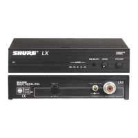
Shure LX4 Diversity Receiver
4
Characteristics
25D1008 (BK)
Independent Rf Sections
Two complete, independent rf sections are provided for diversity
reception. Signals enter the receiver via detachable, single-element
quarter-wave antennas. For diversity channel A, they pass through a
filter that is double-tuned by L100 and L101 before entering dual gate
MESFET amplifier Q100. The output of this stage is triple tuned by
L103, L104, and L105, which filter the signals before they enter gate 1 of
MESFET mixer Q101. The local oscillator (LO) signal, which is applied
to gate 2 of Q101, is provided by transistor Q104. A third- or fifth-
overtone quartz crystal in the 50 to 70 MHz range is used to provide
frequency control. The collector circuit of the oscillator is tuned by
L113 and L114 to the third harmonic of the crystal (150 to 210 MHz)
to provide the correct injection frequency for a 10.7 MHz intermediate
frequency (IF).
The output of mixer Q101 is tuned to 10.7 MHz by L108 before being
applied to ceramic filter FL100. Transistor Q102 provides IF amplification
to make up for filter losses. Signals then pass through a second IF filter,
FL101, before entering the integrated circuit IF amplifier/detector, U100.
The detected audio is taken from pin 8 and is then amplified by opera-
tional amplifier U1A.
Rf Channel B
Diversity channel B is identical in design to channel A. Signals first
pass through a double-tuned filter consisting of L200 and L201 before
entering amplifier Q200. The output of this stage is triple-tuned by L203,
L204, and L205 and fed to gate 1 of mixer Q201. LO injection is pro-
vided by buffer transistor Q103, which is tuned by L112 and L111 to the
third harmonic of the crystal frequency. The buffer stage helps to isolate
the diversity channels from one another by preventing crosstalk through
the common LO section.
The output of mixer Q201 is tuned to 10.7 MHz by L208 before being
applied to ceramic filter FL200. Signals are then amplified by transistor
Q202 before passing through the second ceramic filter, FL201, before
they enter the integrated circuit IF amplifier/detector U200. The detected
audio is again taken from pin 8 and is amplified in this case by U2A.
Rf Indicators
Rf LEDs indicate approximate rf signal strength for each channel:
LED
Signal Strength, dBm (±10 dBm)
1 –95
2 –90
3 –80
4 –65
5 –60
 Loading...