Voltage supply (XD1)
V
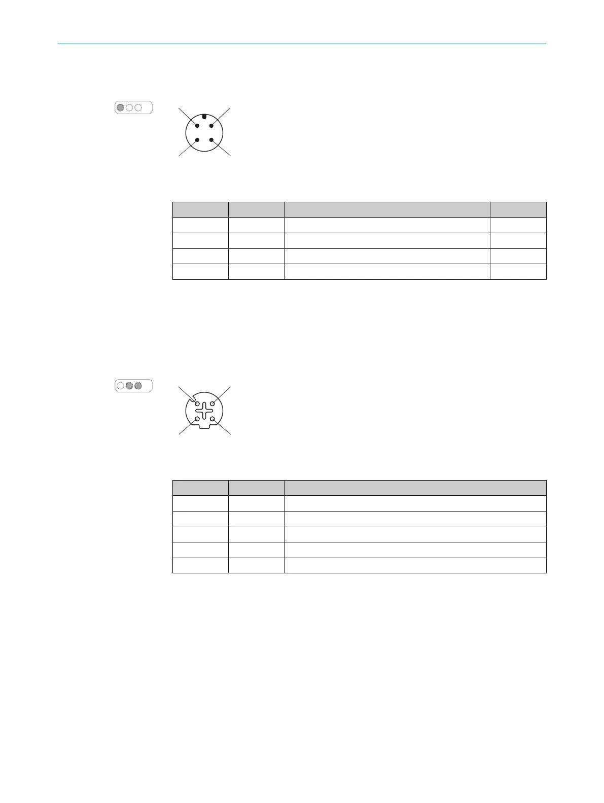
oltage supply is supplied via a 4-pin, A-coding M12 male connector on the device side.
Figure 3: Pin assignment of the voltage supply (male connector, M12, 4-pin, A-coded)
Table 3: Pin assignment of the voltage supply
Pin Marking Function Wire color
1)
1 +24 V DC 24 V DC supply voltage Brown
2 NC Not connected White
3 0 V DC 0 V DC supply voltage Blue
4 FE Functional earth/shield Black
1)
Applies to the connecting cables recommended as accessories.
Ethernet for EFI-pro, data output, configuration, and diagnostics (XF1, XF2)
On t
he device side, Ethernet and EFI-pro are connected via 4-pin, D-coding M12 female
connectors. There is a network switch in the safety laser scanner which connects the
two Ethernet female connectors. The two Ethernet female connectors therefore have
the same function. The pin assignment corresponds to EN 61918, Appendix H.
Figure 4: Ethernet pin assignment (female connector, M12, 4-pin, D-coding)
Table 4: Ethernet pin assignment
Pin Designation Function
1 TX+ Send data +
2 RX+ Receive data +
3 TX– Send data -
4 RX– Receive data -
Housing SH Shielding
5.3 SIM1000 FXA
The electrical installation is described in detail in the operating instructions:
•
8023298
ELECTRICAL INSTALLATION 5
8024819/2019-09-02 | SICK T E C H N I C A L I N F O R M A T I O N | LiDAR Localization Hardware Integration
11
Subject to change without notice

 Loading...


