Annex
106 © SICK AG · Germany · All rights reserved · Subject to change without notice 8012471/ZN27/2017-06-09
Operating Instructions
LMS1xx Laser Measurement Sensors
Chapter 11
11.5 Figures
Fig. 1: Laser output aperture and laser warning label on the LMS1xx ..........................14
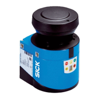
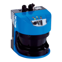
Fig. 2: View of the LMS1xx device variants .....................................................................18
Fig. 3: Status indicators ....................................................................................................21
Fig. 4: Measuring principle of the LMS1xx ......................................................................23
Fig. 5: Principle of operation for pulse propagation time measurement ......................23
Fig. 6: Reflection of the laser beam at the surface of an object ....................................24
Fig. 7: Reflection angle .....................................................................................................24
Fig. 8: Degree of reflection ...............................................................................................25
Fig. 9: Mirror surfaces .......................................................................................................25
Fig. 10: Object smaller than diameter of the laser beam .................................................25
Fig. 11: LMS10x/LMS11x/LMS12x/LMS13x/LMS173/LMS182 and
LMC12x/LMC13: Scanning range as a function of the target remission ..........26
Fig. 12: LMS14x: Scanning range as a function of the target remission ........................26
Fig. 13: Scanning range of the LMS15x as a function of the target remission ...............27
Fig. 14: Beam expansion ....................................................................................................28
Fig. 15: Schematic layout of the distance between measured points
at different angular resolutions ............................................................................28
Fig. 16: All LMS1xx variants: Beam diameter and distance
between measured points at 0 to 20 m ...............................................................29
Fig. 17: LMS14x: Beam diameter and distance
between measured points at 0 m to 40 m ..........................................................30
Fig. 18: LMS15x: Beam diameter and distance
between measured points at 0 to 50 m ...............................................................30
Fig. 19: Minimum object size for detection .......................................................................31
Fig. 20: Effect of the hardware blanking window on the evaluation fields
for the field application ..........................................................................................35
Fig. 21: Measured value telegram request ........................................................................36
Fig. 22: Continuous measured value output .....................................................................37
Fig. 23: Principle of operation of the measurement of the second reflected pulse .......38
Fig. 24: Shading of reflections ............................................................................................39
Fig. 25: Principle of the field application ...........................................................................40
Fig. 26: Protection against tampering due to shading and glare .....................................43
Fig. 27: Examples of different evaluation field shapes .....................................................44
Fig. 28: Logical operators for inputs and outputs .............................................................46
Fig. 29: Increase in the size of the beam and safety supplement ...................................51
Fig. 30: Direct mounting ......................................................................................................57
Fig. 31: Mounting with mounting kit 1a (part no. 2034324) ...........................................58
Fig. 32: Mounting with mounting kit 1b (part no. 2034325) ...........................................58
Fig. 33: Mounting with mounting kit 2 (part no. 2039302)
and kit 3 (part no. 2039303) ................................................................................59
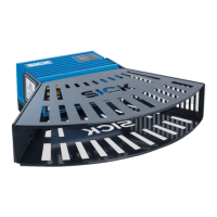
Fig. 34: Weather protection hood 190°(part no. 2046459) ............................................60
Fig. 35: Weather protection hood 270°(part no. 2046458) ............................................60

 Loading...
