Elektrisk installasjon
NO
• Forklaring til elektrisk tabell
- Kabellengder tilsvarer totallengden A+B+C(+D+E), Fig. 12.
- Min. batterikap. som kaldstartkapasitet (CCA) i Ampere, ikke Ampere-
timer.
- Bruk trege sikringer for å forebygge spenningsfall.
• Det er viktig å bruke kabler som er store nok, og et batteri med god
kaldstartkapasitet for å drive thrusteren. Det er spenningen (V) som
kommer frem til motoren under kjøring som bestemmer turtallet til mo-
toren og dermed også skyvekraften. Vær vennlig og jamfør listen over
for minimum anbefalte kabel, og batteristørrelse.
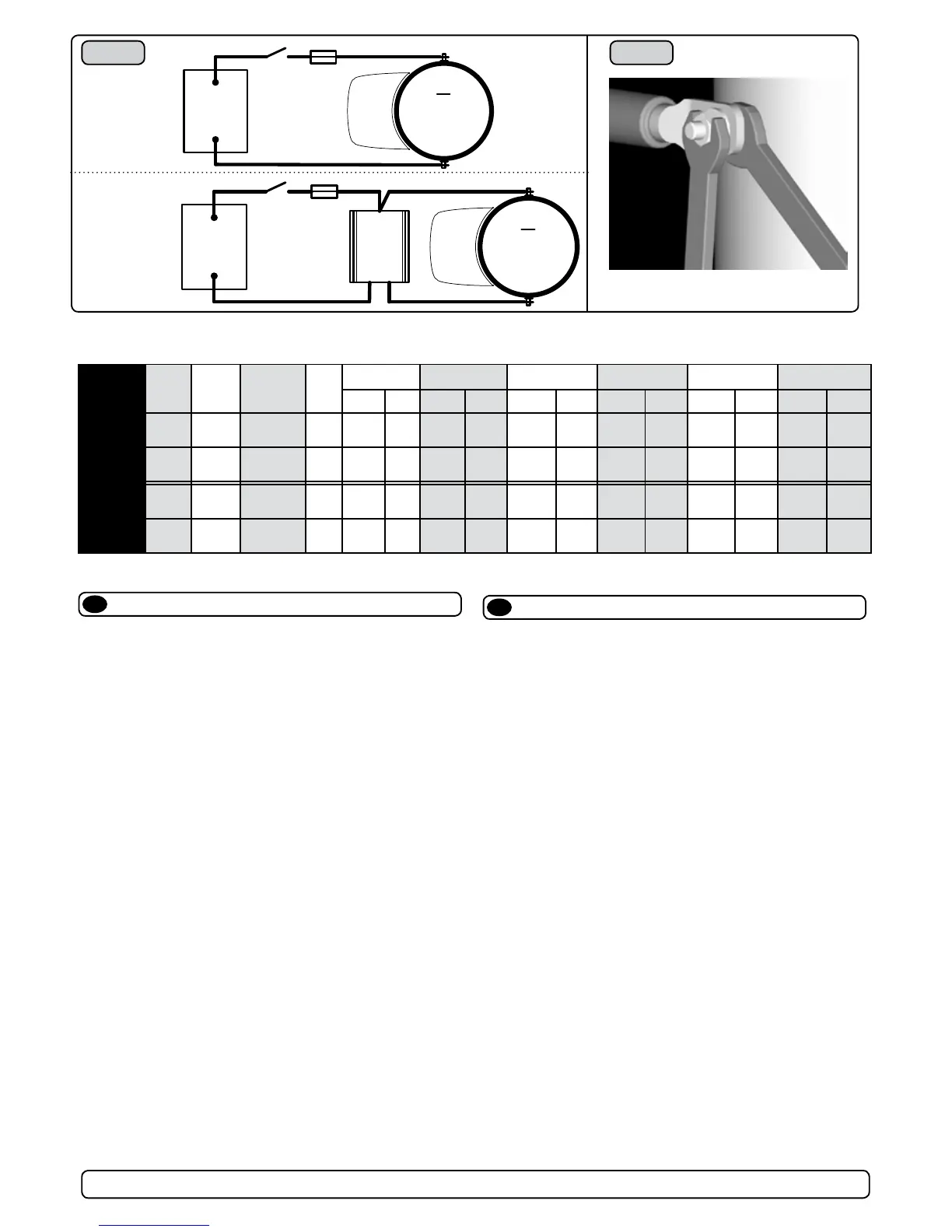
• Koble strømforsyning til motor og controller i følge skjemaene VISUAL
WIRING DIAGRAM for SRV/SRL eller SRVP/SRLP versjon
• En hovedstrømbryter (*C) som ikke medfører stor spenningsfall MÅ
installeres på thrusterens plusskabel slik at det er mulig å skru av
strømmen til thruster uavhengig av resten av det elektriske systemet,
når man ikke er om bord, eller i et nødstilfelle. Bryteren bør plasseres
på et tilgjengelig sted, og båtens instruksmanual må ta for seg at denne
skal skrus av slik som de andre hovedbrytere.
• Det må installeres sikring på pluss strømkabelen for å beskytte mot
kortslutning av hovedstrømkablene. Sikringen bør være av høy kvalitet,
noe som vanligvis betyr at de er fysisk store, for å unngå spenningsfall
som ofte er resultatet av å bruke mindre, enklere sikringer. Sikringen
skal være en treg type som tåler amper trekket til elektromotoren i
minimum 5 min.
• Det anbefales å bruke en S-link styrt automatisk hovedstrømbryter som
inneholder hovedsikring, Sidepower Automatic Main Switch 897712
(12V) eller 897724 (24V).
• Koble strømforsyning til motor og controller i følge skjemaene på side
11 eller 12 alt etter modell.
• Kabelendene må påmonteres terminaler og disse må isoleres mot alt
som ikke er riktig kontaktpunkt.
• Det er viktig att kabelsko trekkes korrekt fast på koblingsbolt. Kontra
mutter på koblingsbolt må holdes fast ved tiltrekking (Fig. 13).
Minus kabelen (*A) tilkobles A1 (-) terminalen.
Pluss kabelen (*B) tilkobles "+" terminalen.
ø10mm / 3/8’’på motoren dra til med 15 Nm.
Electrical installation
EN
Battery & cable recommendations:
• Explanation of electrical table
- All cable lengths are the total of A+B+C(+D+E) in Fig. 12.
- Battery size is stated as minimum cold crank capacity, not Ah.
- Use slow fuse rated to hold stated Amp-Draw for min. 5 minutes.
• It is important that you use a good cable size and batteries with a
high cranking capacity to feed the thruster, because it is the actual
voltage at the motor while running the thruster that decides the
output rpm of the motor and thereby the actual thrust. Please see
the list below for advised min. sizes of cables and batteries. You can
of course use larger cables for even better results.
• Connect the power supply to motor and controller according to dia-
grams VISUAL WIRING DIAGRAM for SRV/SRL or SRVP/SRLP
version
• A main switch that can take the load without noticeable voltage
drop must be installed in the main positive lead so the power for the
thruster can be turned off independent of the rest when not on board
or in emergencies. This should be placed in an easy accessible
place and the boats instructions should inform that this should be
turned off like the boat’s other main switches.
• We also advice to install a fuse in the positive lead for protection
against short circuiting of the main cables. This fuse should be of a
adequate quality which normally means that it is physically large as
these have less voltage drop than the simple / small ones. It should
be of the slow type and sized to take the amperage draw for at least
5 minutes.
• It is highly recommended to install a Sidepower Automatic Main
Switch 897712 (12V) eller 897724 (24V). The AMS will be activated
when the panel is turned on, contains an automatic short circuit fuse
and a manual emergency stop. The AMS will also provide feedback to
the panel regarding evt. faults.
• Connect power supply to the motor and controller according to
schematics on pages 11 or 12 according to model.
• The cable ends must be tted with terminals and these must be well
isolated against contact with anything but the proper connection
point.
• Terminals must be properly tightened. Secure/hold inner nut when
tightening (Fig. 13). Tighten ø10mm / 3/8" bolt with 15 Nm/11lb/ft.
Fig. 12
Fig. 13
SRV/SRL
Models
SRVP/SRLP
Models
Minimum and recommended cable dimensions can be identical due to safety margins and cable heat considerations for short cable lenghts.
 Loading...