Chapter 1 – Hardware
Components
The components of the DPM include:
•
•
•
•
•
Liquid Crystal Display (LCD)
Light Emitting Diodes (LEDs) (2)
Horn Silence Button
Portable Operator’s Terminal Port
Pressure Mode Key Switch (optional)
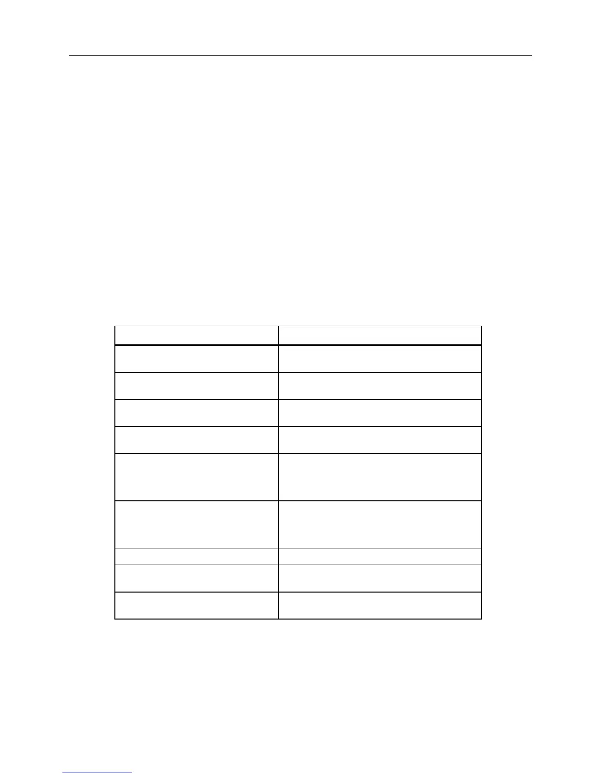
LCD Messages
The LCD shows the differential pressure of the room in inches of H
2
O or Pascals. It also
shows the status of the DPM with the following messages:
LCD Message… Indicates that the…
LOW PRESSURE room differential pressure is below the user-
defined limit.
HIGH PRESSURE room differential pressure is above the user-
defined limit.
DOOR OPEN door to the occupied space is open if it is being
monitored.
GENERAL FAILURE RPT has lost power or the DPM is not receiving
the pressure signal from the RPT.
SWITCH OVERRIDE database points that determine pressurization
mode have been set from a field panel. This
overrides the pressure mode key switch position,
rendering it ineffective.
ANTEROOM LCD is displaying the anteroom pressure in
response to pressing the Horn Silence button, or
anteroom differential pressure is not being
maintained.
NO ISOLATION device is monitoring for neutral pressure.
PROTECTIVE ISOLATION /POSITIVE
PRESSURE
device is monitoring for positive pressure
(Applications 701 and 702).
INFECTIOUS ISOLATION/NEGATIVE
PRESSURE
device is monitoring for negative pressure
(Applications 703 and 704).
Siemens Building Technologies, Inc. 3
 Loading...