3. Fasten the cable lug to the end of the conductor correctly, e.g. by squeezing.
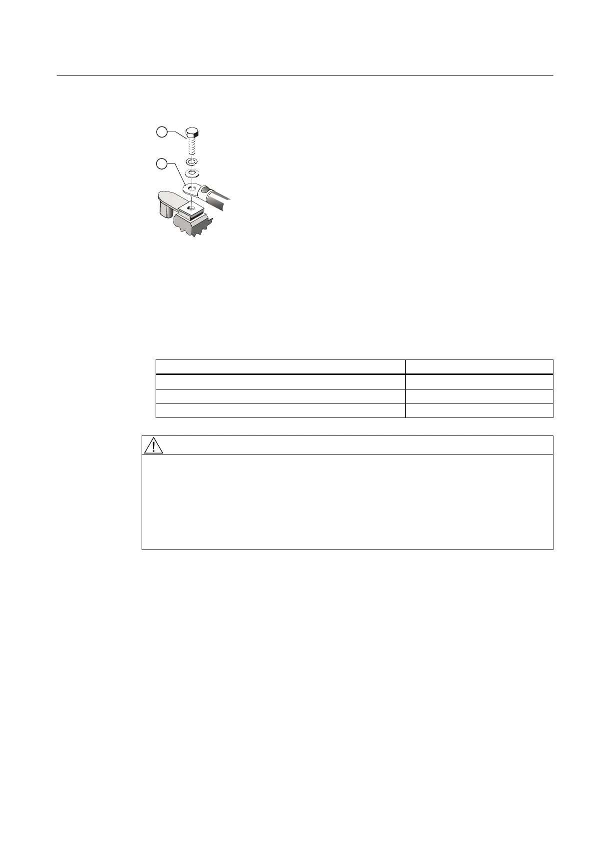
Figure 6-7 Connection with cable lug and fixing screw (schematic diagram)
4. Insulate the cable lug sleeves where necessary to ensure minimum air clearances and the
creepage distance are maintained.
5. Place the cable lug on the terminal support. If you are using a disconnecting link, check its
positioning.
For terminal boxes 1XB7740 and 1XB7750, place the cable lug on the busbar.
6. Tighten the fixing element ② with the corresponding tightening torque:
Fixing element Tightening torque
Fastening screw M12 20 Nm
Fixing screws M16 40 Nm
Fixing nuts M12 20 Nm
WARNING
Explosion hazard if cable lugs without side guards are used
For cable cross-sections under 70 mm
2
, cable lugs without side guard may twist. The
minimum air clearances may be underrun and cause an explosion.
This can result in death, serious injury, or material damage.
● For cable cross-sections under 70 mm
2
, use only cable lugs with side guard.
● Make sure that the minimum air clearances (Page 83) are observed.
6.4.6 Connection without cable lugs
Lug terminal connections - which are suitable for connecting flexible and stranded conductors
without the use of wire end ferrules - may be installed if ordered accordingly. If you wish to
Electrical connection
6.4 Introducing and routing the cables
SIMOTICS TN Series N-compact 1LA8
Operating Instructions 08/2017 79
 Loading...


