8
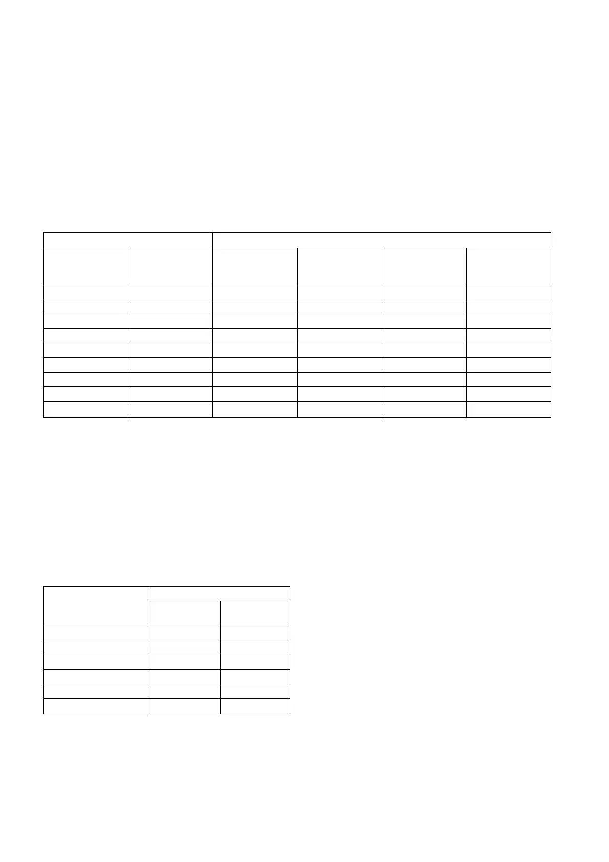
Basic Equipment Supplementary release (at additional cost)
Closing 1st opening 2nd 2nd under- C.T.
release release Opening Opening voltage operated
3AY15 10 3AY15 10 3AY15 10 3AX1101 3AX1103 3AX1102
Y9 Y1 Y3 Y2 Y7 Y4
11
111
11 1
11 11
11 1 1
11 1
11 11
11 1
Table 4: Release Combinations
unlatching mechanism is released and opening of the
circuit-breaker is thus initiated via the stored-energy
mechanism. The stored energy mechanism is
automatically recharged by the circuit-breaker.
The deliberate tripping of the undervoltage release
generally takes place via an NC contact in the tripping
circuit. But it can also be carried out via an NO contact by
short-circuiting of the magnet coil. With this type of
tripping, the short-circuit current is limited by the built-in
resistors.
Undervoltage release can also be connected to voltage
transformers. When the operating voltage drops to
impermissible low levels, the circuit-breaker is tripped
automatically. Power consumption 6.5W or ≤ 7.5VA
4.3.6 Current transformer-operated release (Y4)
3AX1102 (optional feature)
Current transformer-operated (CT-operated) releases
consist of a stored-energy mechanism, an unlatching
mechanism and an electromagnet system. When the
tripping current is exceeded (90% of the CT-operated
release rated current), the unlatching device of the
stored-energy mechanism is released and opening of the
circuit-breaker is thus initiated. In addition to the primary
current transformers, matching transformers are also
required to enable use of the CT-operated releases.
Power consumption for releases with 0.5 A rated tripping
current ≤ 6 VA at 90% of the release rated current and
with open armature.
4.4 Auxiliary switch (S1) 3SV92 (P-14, Fig.11)
The breaker is fitted with 5 NO and 5 NC contacts. It
is actuated by the breaker shaft, and switches the
auxiliary circuits. Optionally, aux. switch with 11NO
and 11NC contacts is also available.
Rated insulation voltage: AC/DC 250 V
Insulation class: C
Current: 10 A
Making capacity: 50 A
Breaking capacity: in accordance with table 3
Voltage [V] Breaking Capacity [A]
resistive inductive
load load
upto 230 AC 10 10
24 DC 10 10
48 DC 10 9
60 DC 9 7
110 DC 5 4
220 DC 2.5 2
Table 3: Breaking capacity of the 3SV92 auxiliary switch
4.5 Mechanical interlocking (optional feature)
The stored-energy mechanisms of the 3AF01 circuit-
breakers can be equipped with a mechanical (Castell)
interlocking facility to interlock with an isolator.
This arrangement has two locks (one each for breaker
and isolator) and one key. Hence when the key is trapped
in the lock of the breaker, the isolator cannot be
operated. However, when the key is removed from the
lock of the breaker, it is in the off position and thus this
lock ensures that breaker cannot be made on. The key
then canbe used to operate the isolator.
 Loading...