3
The operating and pulse duration times stated in Table 2
below apply for 3AF 01 vacuum circuit-breakers:
Operating times:
Opening time, 1st shunt release (Y1) ≤ 65 ms
Opening time, 2nd shunt release (Y3) ≤ 65 ms
Opening time, suppl.shunt release (Y2) ≤ 50 ms
Arcing time <15 ms
Break time, 1st shunt release (Y1) ≤ 80 ms
Break time, 2nd shunt release (Y3) ≤ 80 ms
Break time, suppl.shunt release (Y2) ≤ 65 ms
Close-open time, 1st shunt release (Y1) ≤ 90 ms
Close-open time, 2nd shunt release (Y3) ≤ 90 ms
Close-open time, suppl.shunt release (Y2) ≤ 90 ms
Dead time 300 ms
Closing time with stored-energy mech. ≤ 75 ms
Synchronizing error between the poles ≤ 2 ms
Spring charging times:
Spring charging time (M1) ≤ 15 s
Minimum pulse duration:
Shunt release (Y1) .. 3AY1510 40 ms
Supplementary release 20 ms
(Y2, Y4,Y6) .. 3AX 110_
Closing solenoid (Y9) .. 3AY1510 40 ms
Table 2: Operating and pulse duration times
1320mm creepage is provided on the porcelain
insulators. These are suitable for very high levels of
pollution at site.
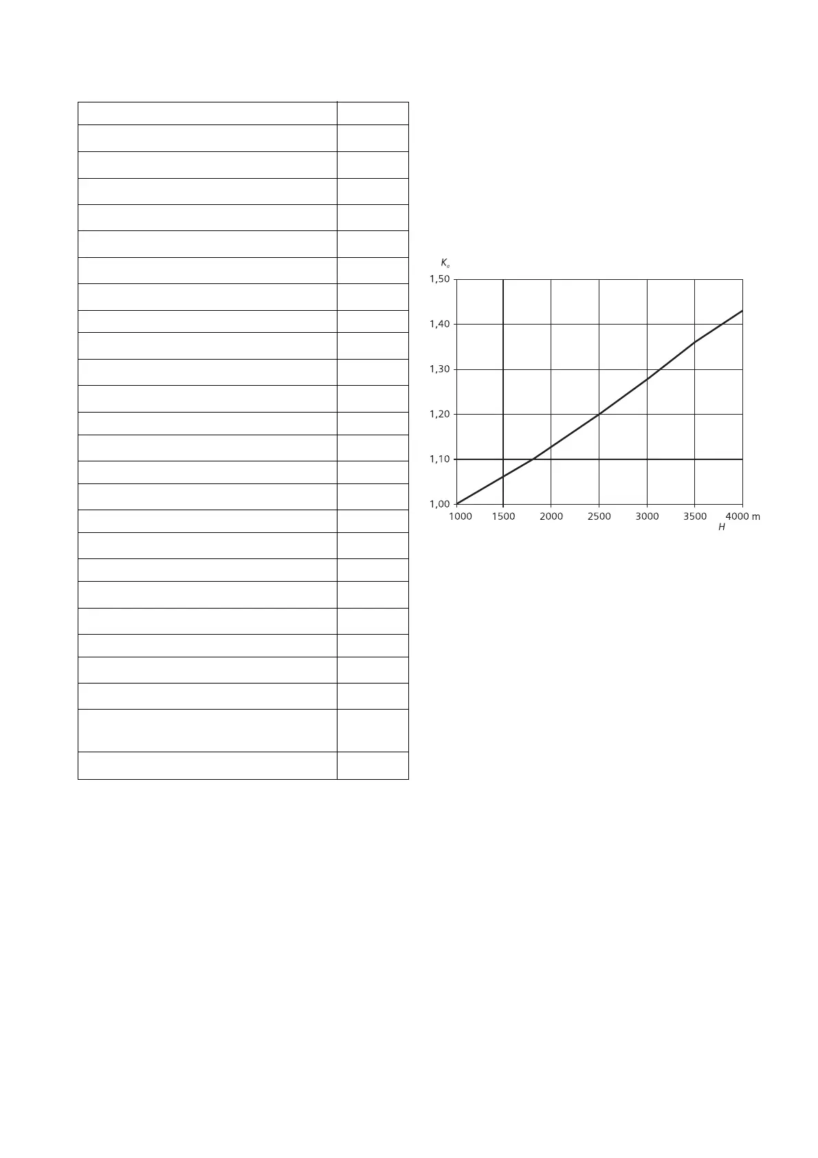
2.3.2 Installation altitude
The insulating capacity of air decreases with rising
altitude due to the lower air density. In conformity with
IEC 62271-1, the rated lightning impulse voltage values
given in Fig. 5 are valid up to an installation altitude of
1000m above mean sea level. As from an altitude of
1000m, the insulation level must be corrected as shown
in Fig. 4:
2.3 Influence of environmental parameters
2.3.1 Permissible ambient conditions
The 3AF 01 vacuum circuit-breakers are designed for the
normal operating conditions laid down in the standards.
Permissible ambient temperatures:
Maximum value + 55
o
C
Average over a period of 24 hours + 35
o
C
Minimum value - 25
o
C
Permissible relative atmospheric humidity:
Maximum value, 24 hour mean 95 %
Maximum value, 1 month mean 90 %
Under these conditions, condensation may occur
occasionally.
Fig. 3: Altitude compensation factor K
a
U ≥ U
o
•
K
a
U Rated withstand voltage V under standard reference
atmosphere
U
o
Required rated withstand voltage for the
installation location
K
a
Altitude compensation factors
K
a
= e
m • (H-1000) / 8150
Calculating the altitude compensation factor K
a
:
H = Installation altitude in meters
m = 1 for AC voltage, lightning impulse voltage
(between the phases, phase-earth, applied
longitudinally)
Example:
For a specified rated withstand voltage of 185kV at an
altitude of 1400m, an insulation level of at least 195kV
under standard reference atmosphere is required:
195kV ≥ 185kV • e
1*(1400-1000)/8150
= 185
•
1.05
This means that equipment designed for a rated voltage
of 195 kV, is required for this application.
 Loading...