10
6. Installation
6.1 Unpacking
CAUTION
The vacuum circuit-breaker may be lifted only by
means of suitable gear attached to the correct points.
Non-compliance can lead to damage.
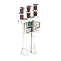
The 3AF 01 outdoor vacuum circuit-breaker is
despatched in one crate. The equipment is protected by
polyethylene sheet while packing. The packing case is
marked with the breaker serial number. A list of items
kept in the case is enclosed with it.
The case contains the base frame (P-2, Fig. 7) with three
pole assemblies (P-1, Fig. 7). These are mounted on
mechanism housing (P-G, Fig. 1). This case also contains
support structure, the foundation bolts (P-4, Fig. 5) nuts
(P-1, Fig. 5), plain washers (P-3, Fig. 5) and spring
washers (P-2, Fig. 5) and any other loose items ordered
separately. The CB is packed and transported with
vacuum interrupters in the open condition. Lifting
instructions and consignee address are marked on the
case.
6.2 Receiving the Equipment
The case nos. should be checked with the despatch
challans before acceptance. The packing case should be
carefully inspected for damage. This should be
immediately brought to the notice of the forwarding
agent and an inventory of damages should also be made
in his presence.
CAUTION
1. Use crane to lift the packing case.
2. Put slings on the marked portion on the packing
case
3. Do NOT topple or tumble the packing case.
6.3 Storage and Handling
It is recommended that the equipment, after removal from
the packing case, be stored in a clean, sheltered area. Care
should be taken against the ingress of water in the
packages. For long time storage, ensure that the space
heater is switched ON.
Refer Fig. 8 for the handling and shifting in a safe manner.
6.4 Erection
The following care will be taken for proper & safe
operation of the breaker.
(1) Use only the bolts supplied.
(2) Use torque wrench for assembly since
unchecked tightening can result in damage to or
loosening of joints.
The necessary torque for screwed joints are as follows:
S. No.
Type of Joint Torque (Nm) ± 10%
Size of Bolt
M8 M10 M12 M20
Property Class
6.6 8.8 8.8 8.8
1 Steel to Steel 32 65 115 –
2 Steel with insulator 16 32 77 170
3 Busbar Joint 20 40 70 –
4 Busbar with Steel 20 40 70 –
Note: The values given in the table above are for
Tightening Torques. For testing the joint, 70% of above
values are to be considered as Checking Torque.
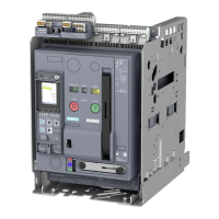
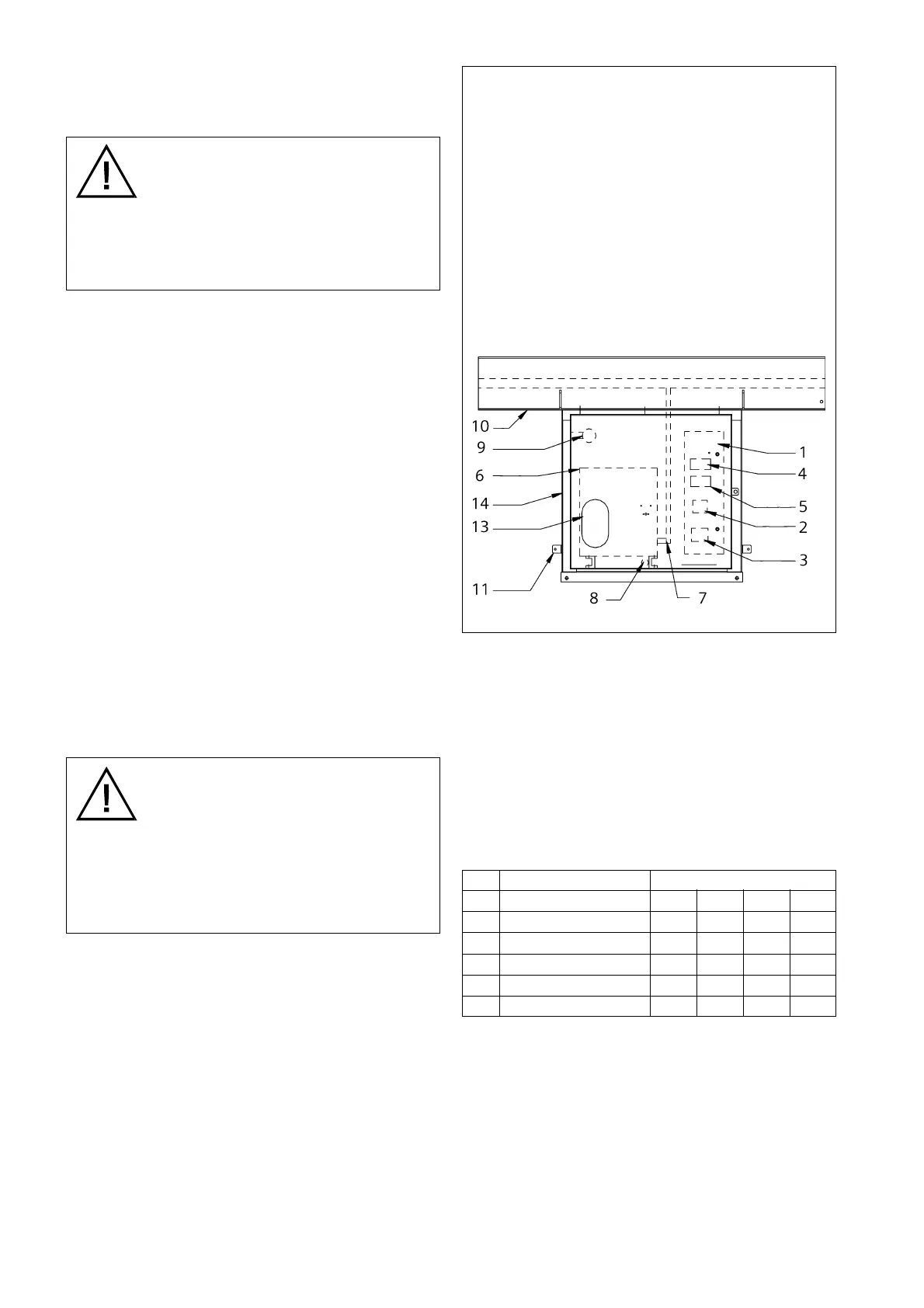
1. Control panel
2. Local/Remove selector switch
3. C.B. ON/OFF switch
4. Terminal blocks
5. Steel structure
6. Operating mechanism
7. Pull rod
8. Transport cover
9. Eye bolt
10.Lever
11.Pin
12. Lock washer
13.Glass window for viewing
mechanical indications
14. Operating mechanism housing
Fig. 10 Baseframe, operating mechanism and control
panel
 Loading...