33 / 60
Siemens Actuators SAS.., SAT.. for valves CE1P4041en
Smart Infrastructure Functions and control 2019-04-09
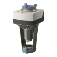
4.2.2 Position feedback U
The position feedback U (DC 0...10 V) is always proportional to stroke H of the
actuator’s stem.
Actuator
Positioning signal Y, Z
Actuator
Position feedback U
lin = linear
log = equal-
percentage
Actuator
Positioning signal Y, Z
Actuator
Position feedback U
Y, Z Positioning signal
H Stroke
U Position feedback
4.2.3 Calibration
To match the actuator to production-related mechanical tolerances of the individual
valves and to guarantee accurate positioning and position feedback, a calibration
should be performed when the plant is commissioned (page 21). During
commissioning, the actuator detects the valve’s end positions and files the exact
stroke in its internal memory.
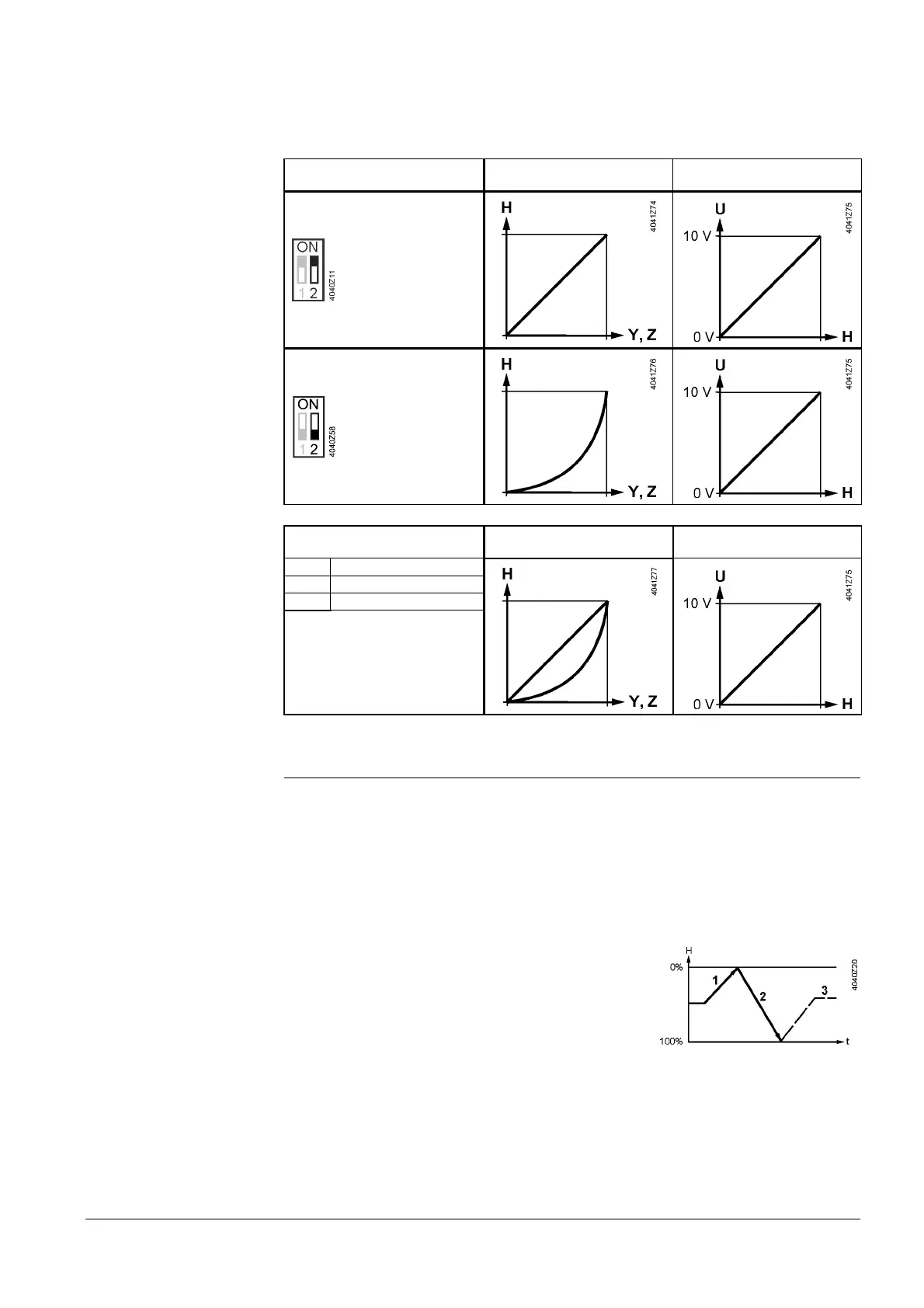
Calibration takes place in the following phases:
· Actuator drives to the upper end position (1),
valve closes. Detection of upper end position.
· Actuator drives to the lower end position (2),
valve opens. Detection of lower end position.
· The detected values are stored (3). Then the
actuator follows the positioning signal.
Observe status indication (LED) during and after calibration (page 43).
Note

 Loading...