34
5.1.1 Selecting the Input/Output Configuration
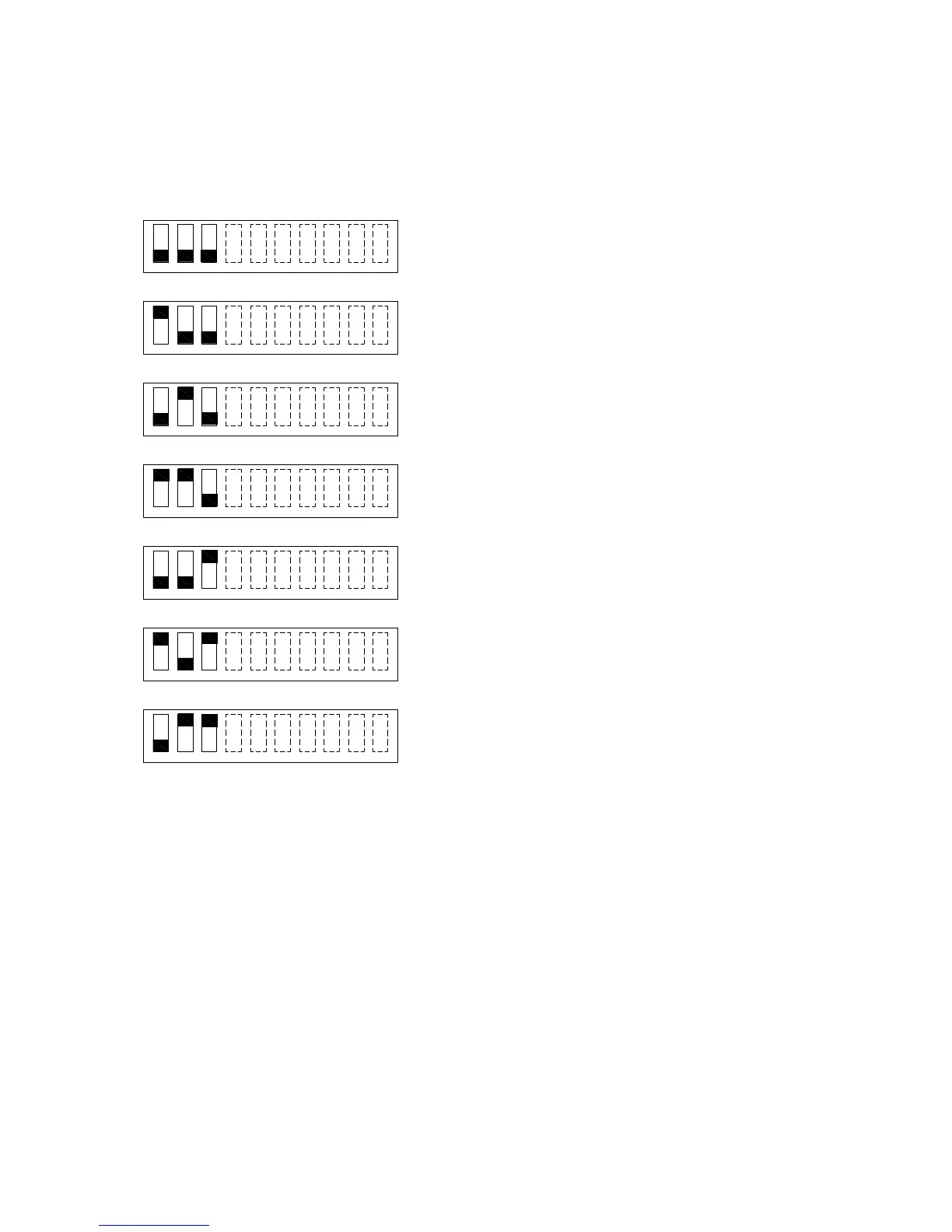
Figure 5-1 shows the position of each switch on the DIP switch for various input and output
configurations. The position of switch 4 through 10 does not affect the relationship of inputs to outputs.
Switch 1 OFF & Switch 2 OFF & Switch 3 OFF:
Input 1 controls all outputs (Class B).
Input 2 not used.
Switch 1 ON & Switch 2 OFF & Switch 3 OFF:
Input 1 controls all outputs (Class B).
Input 2 used to control silencing of Sync horns.
Switch 1 OFF & Switch 2 ON & Switch 3 OFF:
Input 1 controls outputs 1, 2 and 3 (Class B).
Input 2 controls output 4 (Class B).
Switch 1 ON & Switch 2 ON & Switch 3 OFF:
Input 1 controls outputs 1 and 2 (Class B).
Input 2 controls outputs 3 and 4 (Class B).
Switch 1 OFF & Switch 2 OFF & Switch 3 ON:
Input 1 controls outputs 1-2 and 3-4 as Class A.
Input 2 not used.
Switch 1 ON & Switch 2 OFF & Switch 3 ON:
Input 1 controls outputs 1-2 and 3-4 as Class A.
Input 2 used to control silencing of Sync horns.
Switch 1 OFF & Switch 2 ON & Switch 3 ON:
Input 1 controls output 1-2 as Class A.
Input 2 controls output 3-4 as Class A.
Figure 5-1. Setting DIP Switches 1-3
Note: Changing settings for DIP switches 1-3 may affect the settings for jumpers J4-J8.
1 2
3
4
5
6
7
8
9 10
1 2
3
4
5
6
7
8
9 10
1 2
3
4
5
6
7
8
9
10
2 1
3
4
5
6
7
8
9 10
ON
OFF
2 1
3
4 5
6
7
8
9 10
1 2
3
5
4
6
10
7
8
9
2
1
3
4
5
6
7
8
9 10
 Loading...