41
7. COMPATIBLE DEVICES
See Siemens P/N 315-096363 for compatible notification appliances.
8. TROUBLESHOOTING
This section describes the LED states and provides possible trouble conditions of the PAD-3.
8.1 LED INDICATORS
Light-emitting diodes (LEDs) indicate fault and normal conditions. The seven LEDs indicate a fault
condition in one of the circuits (either outputs 1 through 4, auxiliary power, ground fault, or battery). A fault
condition in the LEDs corresponding circuit will turn on the LED (labeled on the board). The POWER LED
will normally be on and turn off to indicate an AC Fail condition. See Figure 2-2 for locations of LEDs.
Their functions are as follows:
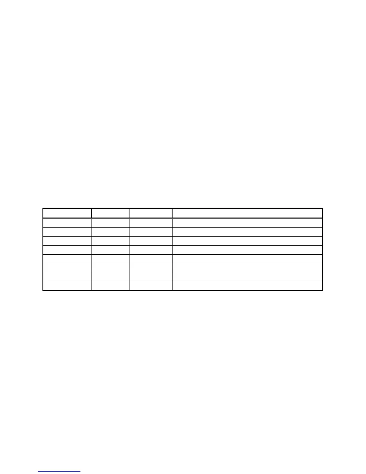
DESIGNATION MARKING COLOR DESCRIPTION
DS1 OUTPUT1 Yellow NAC 1 trouble LED.
DS2 OUTPUT2 Yellow NAC 2 trouble LED.
DS3 OUTPUT3 Yellow NAC 3 trouble LED.
DS4 OUTPUT4 Yellow NAC 4 trouble LED.
DS5 AUX. P.S. Yellow Auxiliary power output trouble LED
DS6 GRND Yellow Ground fault LED
DS7 BATTRY Yellow Battery trouble LED
DS8 POWER Green AC Power normal LED
8.2 IMPROPER OPERATION
If there is improper operation of the activation of the outputs, check for the following:
Was the reset switch SW2 pressed after changing the DIP switch settings?
Are the DIP switch settings correct for the application?
(See Section 5.1)
Are the jumper settings correct for the application?
(See Section 5.2)
Are the inputs activating correctly?
Are the correct type of notification appliances connected?
(Conventional or Sync Strobes/Horns)
 Loading...