Mounting and installation
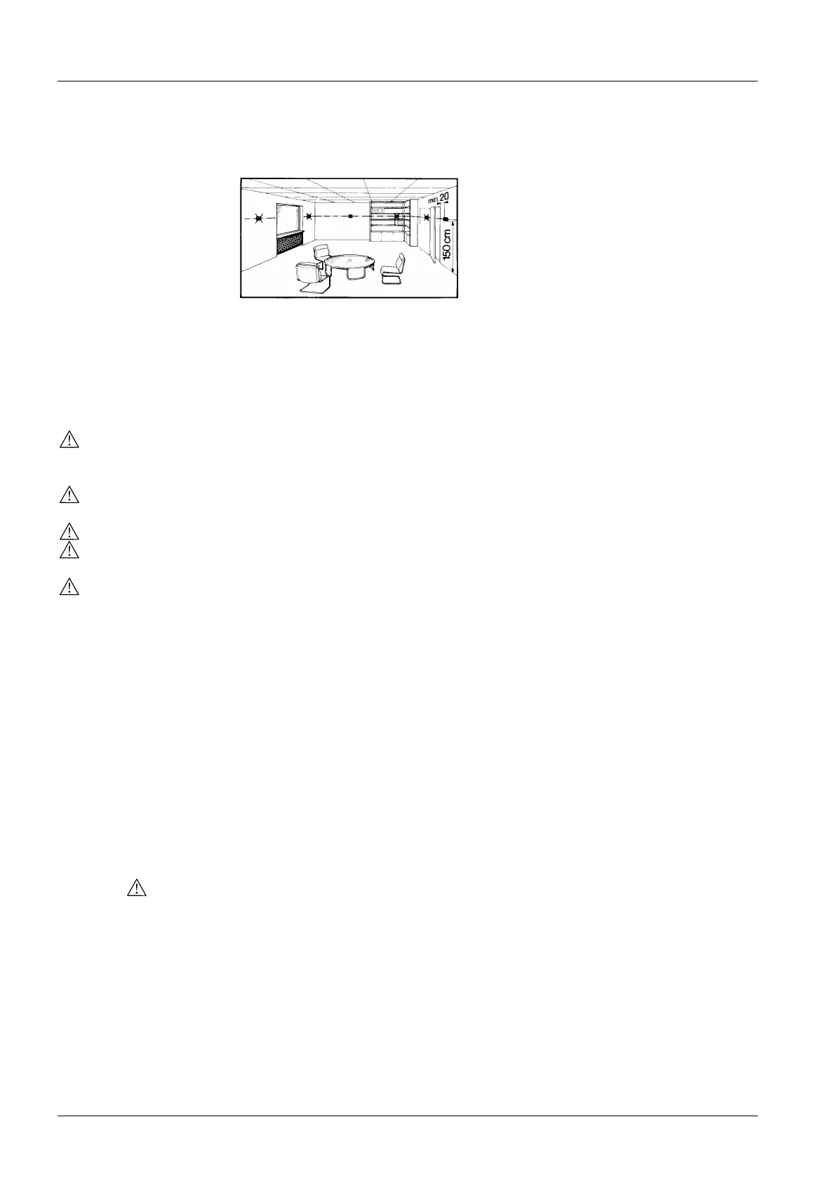
The room controller can be mounted on a wall or inside the fan coil unit. The mounting
location on a wall should not be in niches or bookshelves, not behind curtains, above or
near heat sources and not exposed to direct solar radiation. Mounting height is about
1.5 m above the floor.
The controller can be fitted on a recessed conduit box.
When using a heating / cooling changeover sensor, then, before fitting the sensor,
thermal conductive paste must be applied to the location on the pipe where the sensor
is placed.
Also refer to the Mounting Instructions B3058 enclosed with the controller.
Wiring
• Wiring, fuse and earthing must be installed in compliance with local regulations. It
must be made certain that safety extra low-voltage lines (SELV circuit) are clearly
separated from AC 230 V mains voltage cable
• The cables to the controller, external sensor, fan and valves carry AC 230 V mains
voltage and must be appropriate sized
• Only sensors and valves rated for AC 230 V may be used
• The AC 230 V mains supply line must have an external fuse or circuit breaker with a
rated current of no more than 10 A
• Maximum 10 changeover contact inputs B1-M can be connected in parallel if an
external switch is used in place of a changeover sensor. The switch must be suited
for AC 230 V. The cable length must not exceed 80 m overall
Commissioning
After applying power, the controller makes a reset during which all LCD segments flash,
indicating that the reset has been correctly made. This takes about 3 seconds. Then,
the controller is ready for commissioning by qualified HVAC staff. The control parame-
ters of the controller can be set to ensure optimum performance of the whole system
(also refer to “Setting the control parameters”).
• Only with RDF210: Depending on the application, the heating / cooling mode must
be set via parameter P22. Factory setting is “Cooling only”. When using the ”Auto-
matic heating / cooling changeover” function, P22 must be set to “Automatic H/C
changeover”.
Note: When P22 is set to “Automatic H/C changeover”, the integrated sensor is
used for acquiring the room temperature
Heating / cooling mode
• If the controller is used in conjunction with a compressor, the minimum output on
time (parameter P15) and off time (parameter P16) of Y11 must be adjusted in order
not to harm the life time of the compressor
Compressor-based
application
• If the room temperature displayed by the controller dos not accord with the room
temperature effectively measured, the temperature sensor can be recalibrated. In
that case, parameter P07 must be changed
Calibrating the sensor
• For comfort and energy saving reasons, it is suggested to review the setpoints and
setpoint ranges (parameters P01…P06) and, if necessary, to change them accord-
ingly
Setpoint and range
limitation
• Only with RDF210: Parameters P98 and P99 are diagnostic values and help check
the system. With P98, the status of the active temperature sensor is shown and,
with P99, the status of the heating / cooling changeover sensor
Diagnostic values
12/15
Building Technologies Room Temperature Controllers N3058en
HVAC Products 10.01.2006
 Loading...