RUGGEDCOM RS900G
Installation Guide
Chapter 2
Installing the Device
Connecting Low DC Power 9
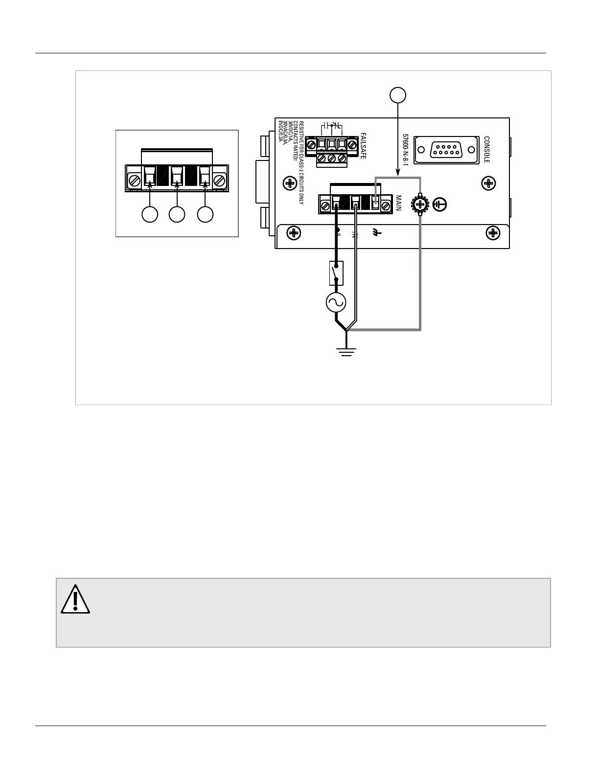
Figure 5: Terminal Block Wiring
1. Positive/Live (+/L) Terminal 2. Negative/Neutral (-/N) Terminal 3. Surge Ground Terminal 4. Braided Ground Cable
2. Connect the negative wire from the power source to the negative/neutral (-/N) terminal on the terminal block.
3. Using a braided wire or other appropriate grounding wire, connect the surge ground terminal to the chassis
ground connection. The surge ground terminal is used as the ground conductor for all surge and transient
suppression circuitry internal to the unit.
4. Connect the ground terminal on the power source to the chassis ground terminal on the device.
Section 2.2.2
Connecting Low DC Power
The RUGGEDCOM RS900G features a single low DC power supply, which accepts input one or more DC power
sources. The use of both power supply inputs is recommended to provide redundancy.
CAUTION!
Electrical hazard – risk of damage to equipment. Before testing the dielectric strength (HIPOT) in the
field, remove the braided ground cable connected to the surge ground terminal and chassis ground.
This cable connects transient suppression circuitry to chassis ground and must be removed to avoid
damage to transient suppression circuitry during testing.
To connect a low DC power supply, do the following:
1. Connect the positive wire from the power source to the positive terminal on either terminal block.
 Loading...