Installing the Device
2.4Mounting the Device
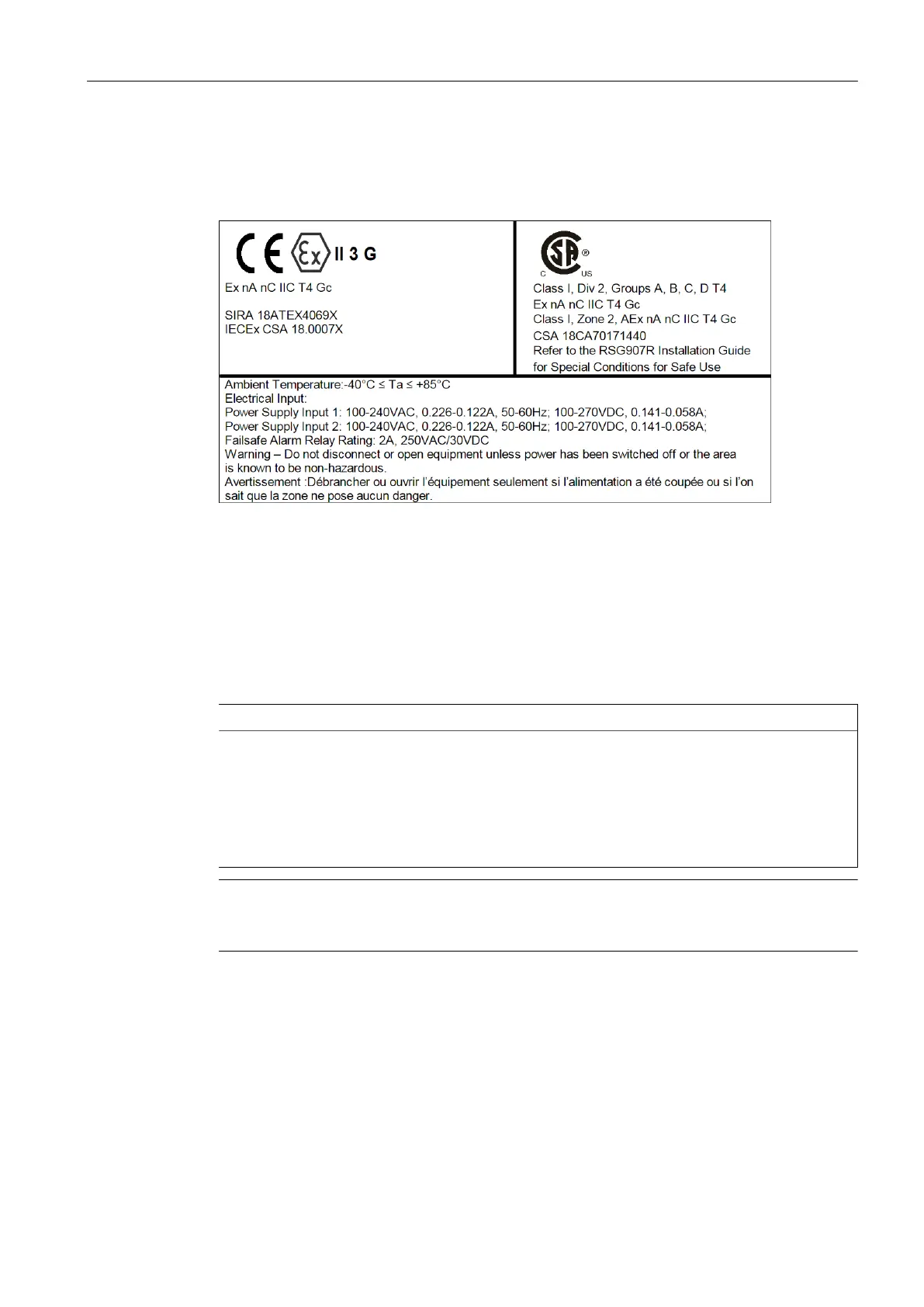
Sample Hazardous Location Label
The following is an example of the RUGGEDCOM RSG907R hazardous location label:
Figure2.1 Compliance Label (Example)
2.4 Mounting the Device
The RUGGEDCOM RSG907R is designed for maximum mounting and display
flexibility. It can be equipped with adapters that allow it to be attached to a DIN rail
or panel.
IMPORTANT
Heat generated by the device is channeled outwards from the enclosure. As such, it
is recommended that 2.5 cm (1 in) of space be maintained on all open sides of the
device to allow for some convectional airflow.
Forced airflow is not required. However, any increase in airflow will result in a
reduction of ambient temperature and improve the long-term reliability of all
equipment mounted in the rack space.
Note
For detailed dimensions of the device with either DIN rail or panel hardware installed,
refer to "Dimension Drawings (Page 34)".
2.4.1 Mounting the Device on a DIN Rail
The RUGGEDCOM RSG907R can be ordered with a DIN rail adapter preinstalled on the
back of the chassis. Use the adapter to mount the device to a standard 35 mm (1.4
in) by 15 mm (0.6 in) IEC/EN 60715 or TS35 DIN rail.
8
RUGGEDCOM RSG907R
Installation Manual, 02/2021, C79000-G8976-1387-12
 Loading...