Installing the Device
2.4Connecting the Failsafe Alarm Relay
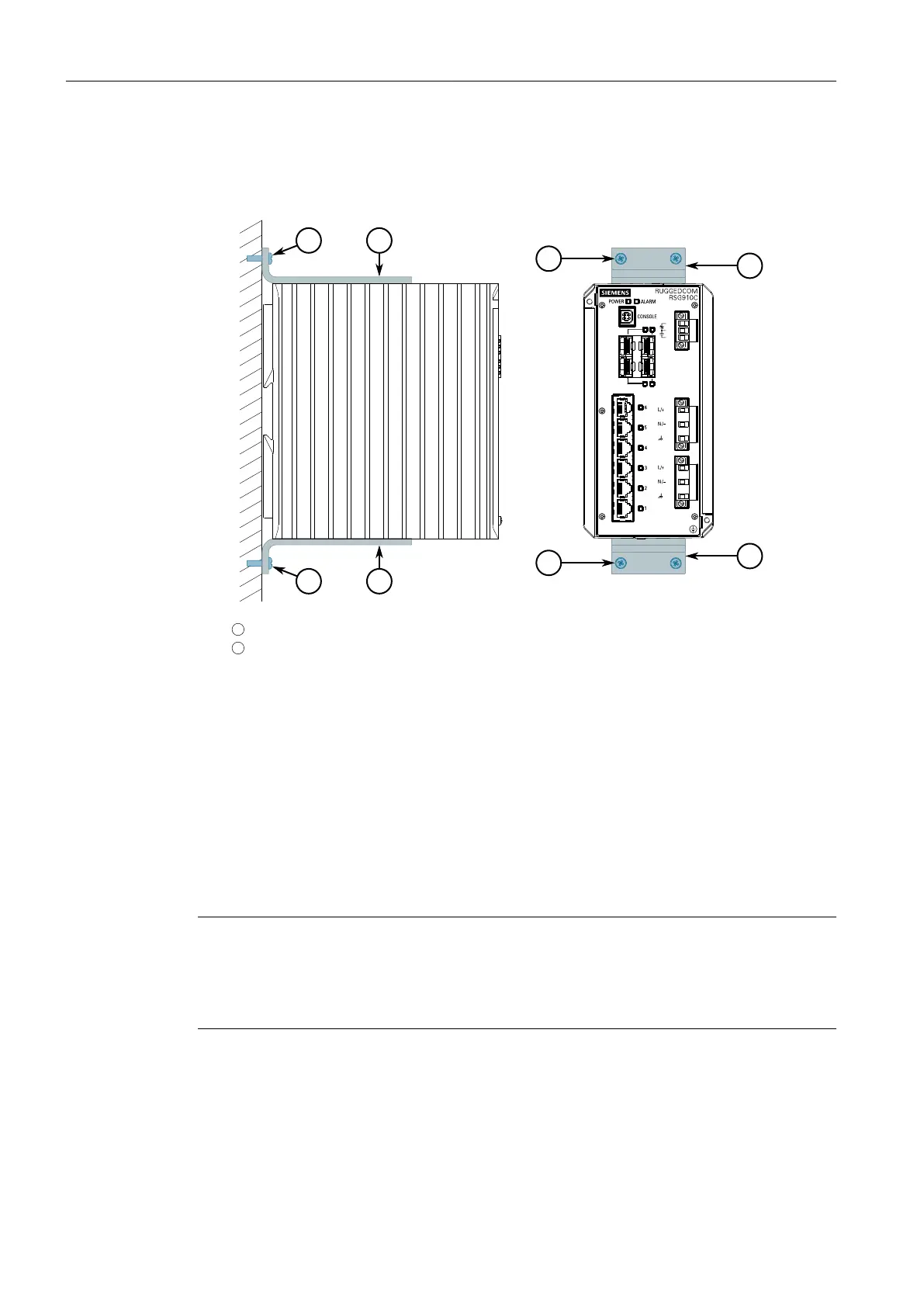
3. Place the device against the panel and align the adapters with the mounting
holes.
1
Screw (M5 or #10-24)
2
Panel Mount Adapter
Figure2.5 Panel Mounting (Rear Mount Orientation)
4. Secure the adapters to the panel with M5 or #10-24 screws.
2.4 Connecting the Failsafe Alarm Relay
The failsafe relay can be configured to latch based on alarm conditions. The NO
(Normally Open) contact is closed when the unit is powered and there are no ac-
tive alarms. If the device is not powered or if an active alarm is configured, the relay
opens the NO contact and closes the NC (Normally Closed) contact.
Note
Control of the failsafe relay output is configurable through RUGGEDCOM RSG910C .
One common application for this relay is to signal an alarm if a power failure oc-
curs. For more information, refer to the RUGGEDCOM RSG910C User Guide for the
RUGGEDCOM RSG910C.
RUGGEDCOM RSG910C
Installation Manual, 02/2020, C79000-G8976-1405-06
11
 Loading...