Installing the Device
2.5Connecting Power
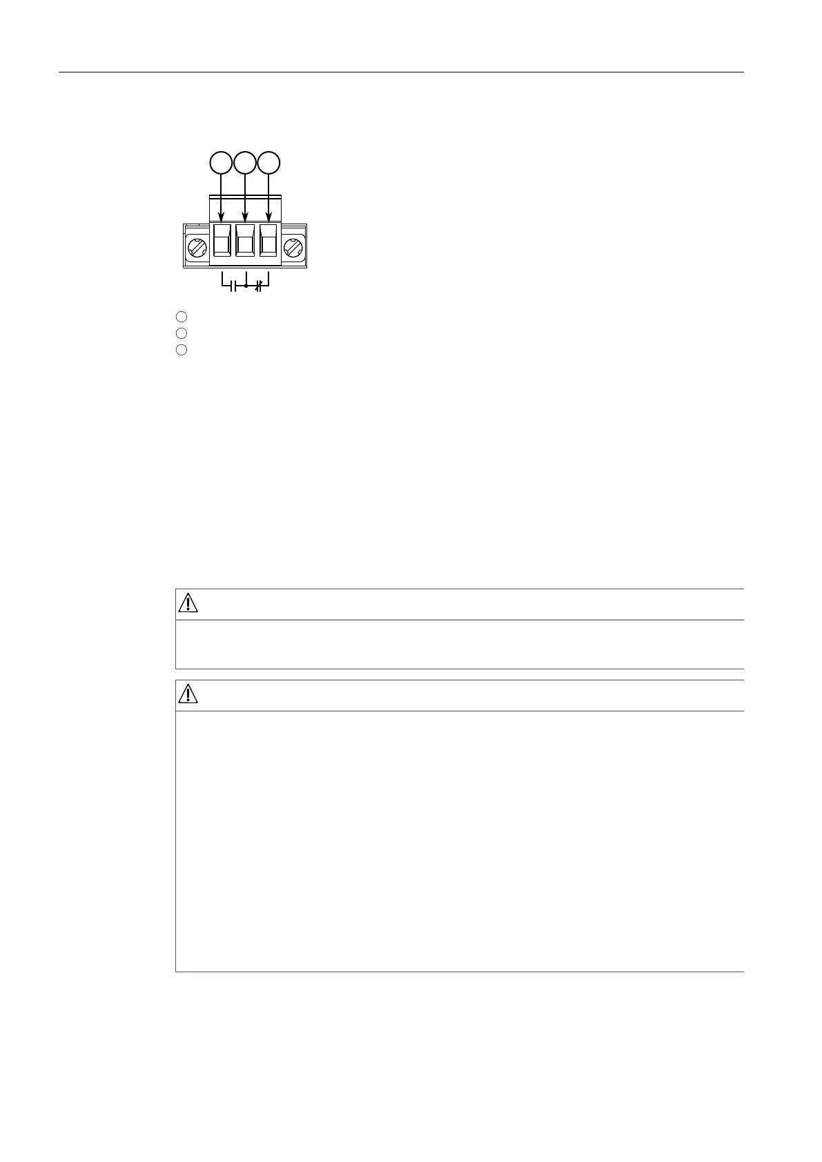
1
Normally Open
2
Common
3
Normally Closed
Figure2.4 Failsafe Alarm Relay Wiring
2.5 Connecting Power
Power modules can be equipped with either a screw or European-style (Euroblock)
terminal block. The screw terminal block is installed using Phillips screws and
compression plates, allowing either bare wire connections or crimped terminal lugs.
For information about installing or removing a power module, refer to "Installing/
Removing Power Modules (Page 40)".
DANGER
Electrocution hazard – risk of serious personal injury or death
Make sure all power sources are off before servicing the power module terminals.
NOTICE
• Use minimum #16 gage copper wiring when connecting terminal blocks.
• The maximum wire length between the terminal block and power source must
not exceed 6 m (20 ft) for 24 V power supplies or 18 m (60 ft) for 48 V power
supplies.
• For 125/230 VAC rated equipment, an appropriately rated AC circuit breaker
must be installed.
• For 125/250 VDC rated equipment, an appropriately rated DC circuit breaker
must be installed.
• It is recommended to provide a separate 20 A circuit breaker for each power
module module.
• Equipment must be installed according to applicable local wiring codes and
standards.
RUGGEDCOM RX1524
Installation Manual, 04/2021, C79000-G8976-1487-02
11
 Loading...