Siemens Industry, Inc.
Building Technologies Division
P/N 315-050537-32
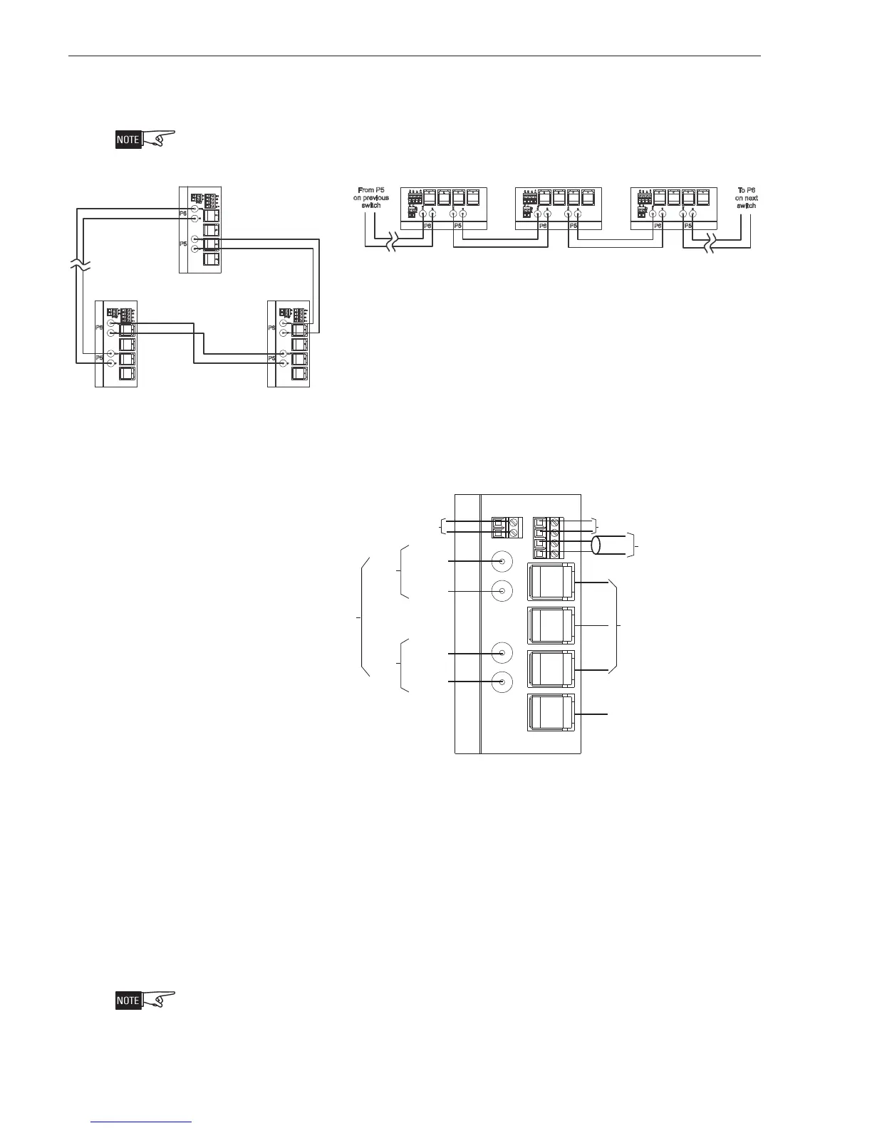
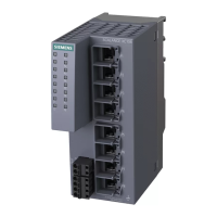
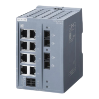
WIRING Figure 4 shows the fiber switch module block wiring diagrams for both Style 7 (Class
X) and Style 4 (Class B). Figure 5 shows the wiring for the Fiber Switch connections
in Style 7 and Style 4 (Class B).
All connectAll connect
All connectAll connect
All connect
ions are supervised and powerions are supervised and power
ions are supervised and powerions are supervised and power
ions are supervised and power
limit limit
limit limit
limit
ed unless sted unless st
ed unless sted unless st
ed unless st
atat
atat
at
ed otherwise.ed otherwise.
ed otherwise.ed otherwise.
ed otherwise.
P1
P2
P3
P4
IN
OUT
IN
OUT
FAU LT
F1
F2
L1+
M1
L2+
M2
SIEMENS
P1
P2
P3
P4
IN
OUT
IN
OUT
FAU LT
F1
F2
L1+
M1
L2+
M2
SIEMENS
P1
P2
P3
P4
IN
OUT
IN
OUT
FAULT
F1
F2
L1+
M1
L2+
M2
SIEMENS
P
1
P
2
P
3
P
4
I
N
O
U
T
I
N
O
U
T
F
A
U
L
T
F
1
F
2
L
1
+
M
1
L
2
+
M
2
S
I
E
M
E
N
S
P
1
P
2
P
3
P
4
I
N
O
U
T
I
N
O
U
T
F
A
U
L
T
F
1
F
2
L
1
+
M
1
L
2
+
M
2
S
I
E
M
E
N
S
P
1
P
2
P
3
P
4
P5
I
N
O
U
T
I
N
O
U
T
F
A
U
L
T
F
1
F
2
L
1
+
M
1
L
2
+
M
2
S
I
E
M
E
N
S
P6
P5
P6
P5
P6
P5
P6
P5
P6
P5
P6
From P5
on previous
switch
To P6
on next
switch
Style 4 (Class B) Block Wiring Diagram
Style 7 Block Wiring Diagram
Figure 4
Style 7 and Style 4 (Class B) Block Wiring of Fiber Switch Module
P1
P2
P3
P4
P5
P6
IN
OUT
IN
OUT
FAULT
F1
F2
L1+
M1
L2+
M2
NEXT
SWITCH
TO P5 IN
TO P5 OUT
FROM P6 IN
FROM P6 OUT
OPTIONAL CONNECTIONS
TO ONE OR MORE:
1. ADDITIONAL VNT
2. NCC
3. SMOKE CONTROL
CATEGORY 5 RJ45 CABLE
LESS THAN 20 FT. IN CONDUIT
OPTIONAL CONNECTIONS
TO
ONE OR MORE:
1. ADDITIONAL VNT
2.
NCC
3.
SMOKE CONTROL
CATEGORY 5
RJ45 CABLE
LESS THAN
20 FT. IN CONDUIT
PREVIOUS
SWITCH
CATEGORY 5 RJ45 CABLE
LESS THAN 20 FT. IN CONDUIT
CATEGORY 5 RJ45 CABLE
LESS THAN
20 FT. IN CONDUIT
SIEMENS
POWER
LIMITED
DO NOT USE
DO NOT USE
MAXIMUM
ATTENUATION
6dB
NOTE:
FOR STYLE 4 (CLASS B)
OMIT CONNECTION
BETWEEN FIRST AND
LAST FIBER SWITCH.
NOTE:
FOR
STYLE 4 (CLASS B)
OMIT CONNECTION
BETWEEN
FIRST AND
LAST FIBER
SWITCH.
Figure 5
Fiber Switch Style 7 and Style 4 (Class B) Wiring Connections
Refer to Figure 6 for the wiring of the fiber switch in a VNT-Building configuration.
Figure 7 shows the wiring of the fiber switch in a VNT-FCC (Fire Command Center)
configuration. Refer to Figures 10 and 11 for the wiring of the fiber switch to PAD-3
and PAD-4 and Siemens Building Management System.
Fiber Connections Two fiber optic cables are required between each pair of fiber switch modules. Use a
high quality duplex fiber optic cable containing 62.5/125 or 50/125 multimode fiber or
g/125 for single mode fiber. Duplex fiber optic cable has two cables in a single
shield similar to electrical zip cord. Use ST style fiber connectors.
Please contPlease cont
Please contPlease cont
Please cont
act the fiberact the fiber
act the fiberact the fiber
act the fiber
cable manufact cable manufact
cable manufact cable manufact
cable manufact
urerurer
urerurer
urer
reg reg
reg reg
reg
arding instructarding instruct
arding instructarding instruct
arding instruct
ions forions for
ions forions for
ions for
t t
t t
t
erminaterminat
erminaterminat
erminat
inging
inging
ing
the fiberthe fiber
the fiberthe fiber
the fiber
..
..
.
R R
R R
R
eferefer
eferefer
efer
to S to S
to S to S
to S
calance X-20calance X-20
calance X-20calance X-20
calance X-20
0 Operat0 Operat
0 Operat0 Operat
0 Operat
ing Instructing Instruct
ing Instructing Instruct
ing Instruct
ions,ions,
ions,ions,
ions,
C790 C790
C790 C790
C790
0
0
00
0
0-G8970-G897
0-G8970-G897
0-G897
6-C284-05,6-C284-05,
6-C284-05,6-C284-05,
6-C284-05,
forfor
forfor
for
addit addit
addit addit
addit
ional informational informat
ional informational informat
ional informat
ion on fiberion on fiber
ion on fiberion on fiber
ion on fiber
opt opt
opt opt
opt
ic switcic switc
ic switcic switc
ic switc
heshes
heshes
hes