Cycle and reaction times
5.3 Response time
CPU 31xC and CPU 31x, Technical Data
5-14 Manual, 01/2006 Edition, A5E00105475-06
DP cycle times in the PROFIBUS DP network
If you have configured your PROFIBUS DP master system in STEP 7, STEP 7 calculates the
typical DP cycle time to be expected. You can then view the DP cycle time of your
configuration on the PG.
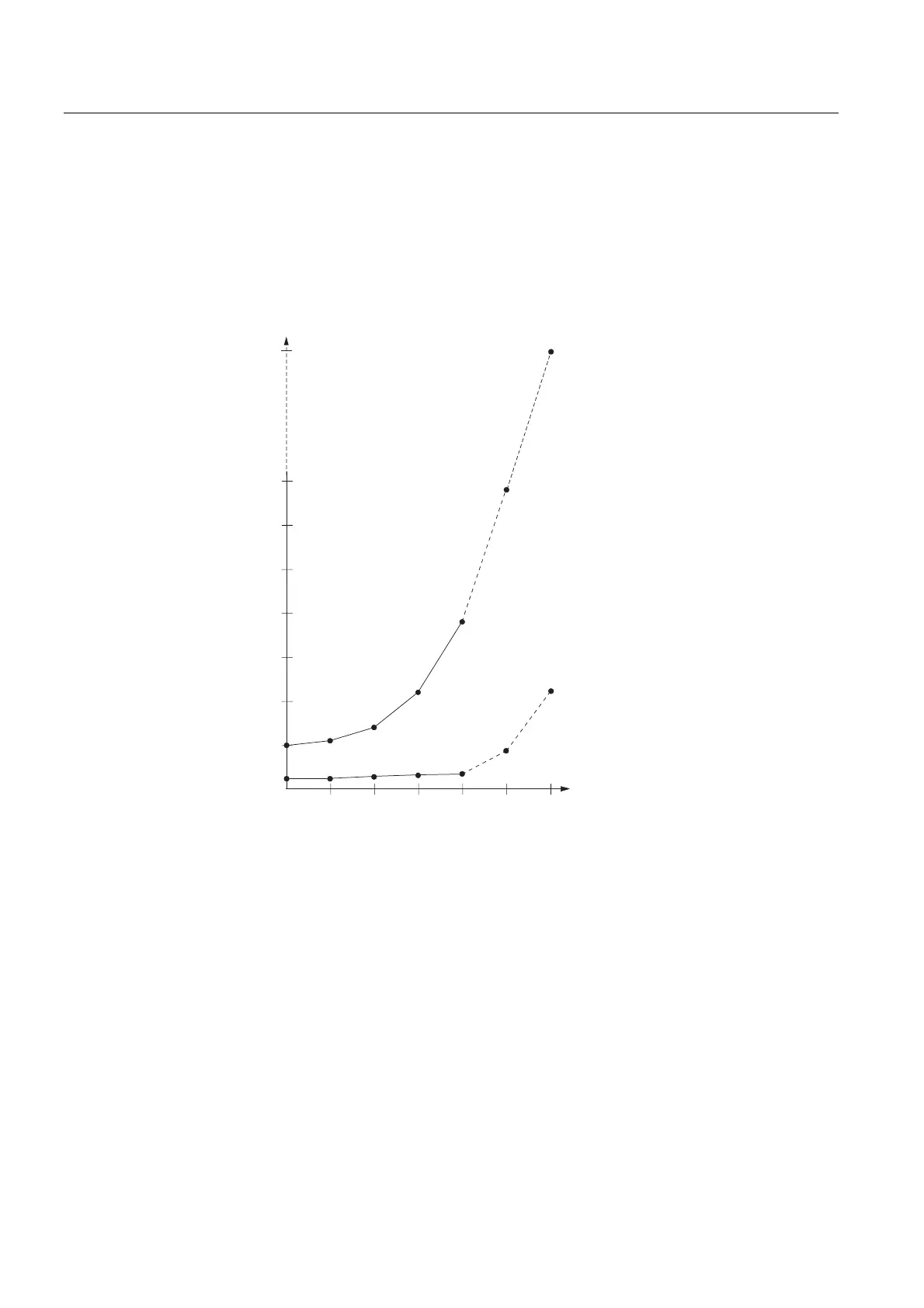
The figure below gives you an overview of the DP cycle time. In this example, let us assume
that the data of each DP slave has an average length of 4 bytes.
PV
PV
PV
PV
PV
PV
PV
PV
%XVUXQWLPH
7UDQVPLVVLRQUDWH0ELWV
7UDQVPLVVLRQUDWH0%LWV
1XPEHURI'3VODYHVPD[LPXP
QXPEHULVGHSHQGHQWRQ&38
0LQLPXP
VODYHLQWHUYDO
With multi-master operation on a PROFIBUS-DP network, you must make allowances for the
DP cycle time at each master. That is, you will have to calculate the times for each master
separately and then add up the results.
 Loading...


