Operating and display elements
2.1 Operating and display elements: CPU 31xC
CPU 31xC and CPU 31x, Technical Data
2-4 Manual, 01/2006 Edition, A5E00105475-06
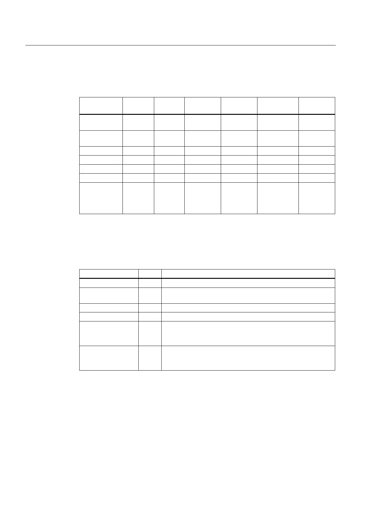
Differences between the CPUs
Table 2-2 Differences of the CPUs 31xC
Element CPU
312C
CPU
313C
CPU
313C-2 DP
CPU
313C-2 PtP
CPU
314C-2 DP
CPU
314C-2 PtP
9-pole DP
interface (X2)
– – X – X –
15-pole PtP
interface (X2)
– – – X – X
Digital inputs 10 24 16 16 24 24
Digital outputs 6 16 16 16 16 16
Analog inputs – 4 + 1 – – 4 + 1 4 + 1
Analog outputs – 2 – – 2 2
Technological
functions
2 counters 3 counters 3 counters 3 counters 4 counters
1 channel for
positioning
4 counters
1 channel
for
positioning
2.1.2 Status and Error Indicators: CPU 31xC
LED designation Color Meaning
SF red Hardware or software error
BF (for CPUs with DP
interface only)
red Bus error
DC5 V green 5-V power for CPU and S7-300 bus is OK
FRCE yellow Force job is active
RUN green CPU in RUN
The LED flashes during STARTUP at a rate of 2 Hz, and in HOLD
state at 0.5 Hz.
STOP yellow CPU in STOP and HOLD or STARTUP
The LED flashes at 0.5 Hz when the CPU requests a memory reset,
and during the reset at 2 Hz.
Reference
• CPU operating modes:
STEP 7 Online Help
.
• Information on CPU memory reset:
Operating instructions CPU 31xC and CPU31x,
Commissioning, Commissioning Modules, CPU Memory Reset by means of Mode
Selector Switch
• Evaluation of the LEDs upon error or diagnostic event:
Operating Instructions CPU 31xC
and CPU 31x, Test Functions, Diagnostics and Troubleshooting, Diagnostics with the
help of Status and Error LEDs
 Loading...


