Operating and display elements
2.2 Operating and display elements: CPU 31x
CPU 31xC and CPU 31x, Technical Data
Manual, 01/2006 Edition, A5E00105475-06
2-11
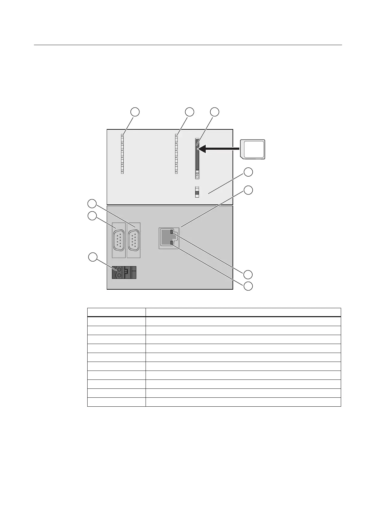
2.2.4 Operating and display elements: CPU 319-3 PN/DP
Operating and display elements
1 2 3
4
8
00&
%)
;
0$&$''
;;;
;;;
;
6723
581
)5&(
'&9
6)
%)
05(6
6723
581
%)
;
5
6
9
7
10
The figures show the following CPU elements
(1) Bus error indicators
(2) Status and error displays
(3) Slot for the SIMATIC Micro Memory Card (MMC) incl. the ejector
(4) Mode selector switch
(5) 3. Interface X3 (PN)
(6) Green LED (LED designation: LINK)
(7) Yellow LED (LED designation: RX/TX)
(8) Power supply connection
(9) 1. Interface X1 (MPI/DP)
(10) 2. Interface X2 (DP)
 Loading...


