Technical data of CPU 31xC
6.6 Technical data of the integrated I/O
CPU 31xC and CPU 31x, Technical Data
Manual, 01/2006 Edition, A5E00105475-06
6-37
PV
PV
PV
PV
PV
PV
PV
PV
PV
PV
9DOXH
9DOXH 9DOXH
9DOXH
9DOXH
9DOXH
9DOXH 9DOXH
9DOXH
9DOXH
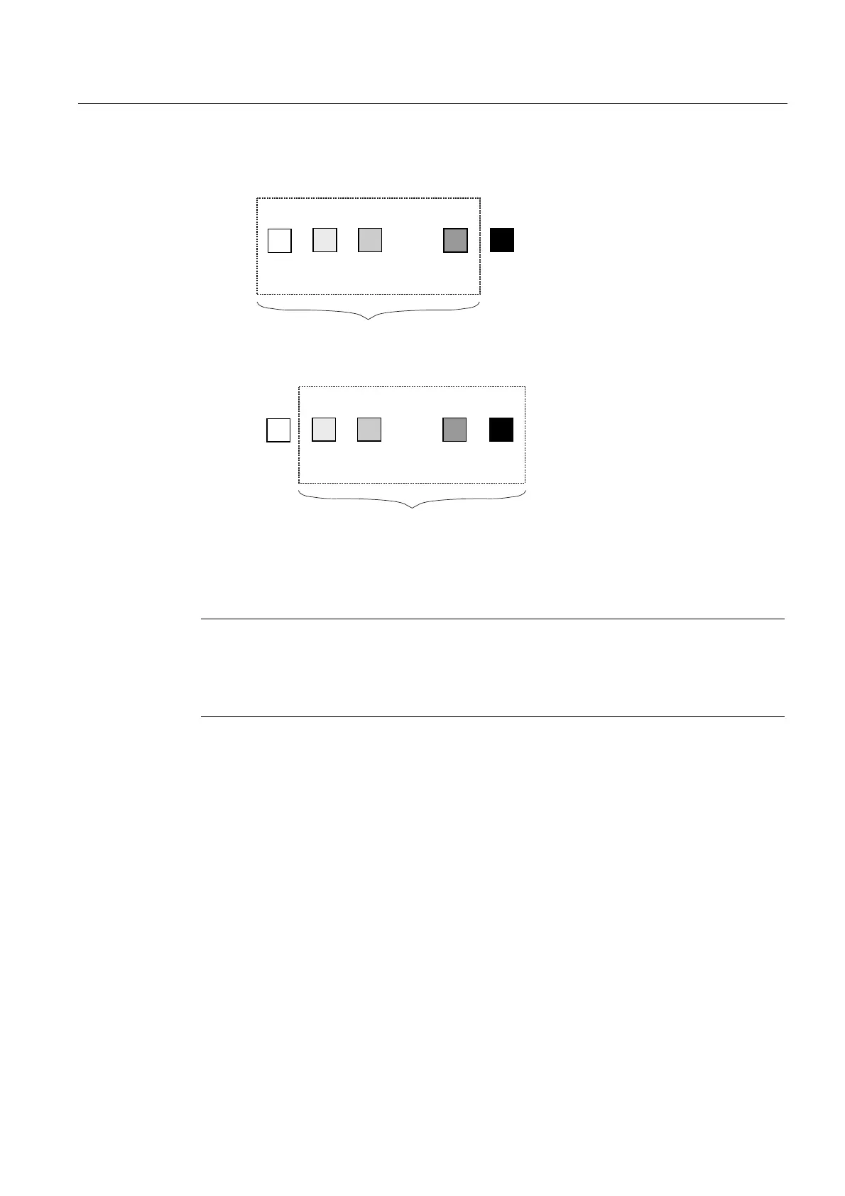
([DPSOHRID+]SDUDVLWLFIUHTXHQF\VXSSUHVVLRQLQWHJUDWLRQWLPHFRUUHVSRQGVWRPV
DYHUDJHGPHDVXUHGYDOXH
DYHUDJHGPHDVXUHGYDOXH
&\FOH
&\FOH
Figure 6-6 60 Hz interference suppression
Note
If the interference frequency is not 50/60 Hz or a multiple thereof, the input signal must be
filtered externally,
In this case, 400 Hz frequency suppression must be configured for the respective input. This
is equivalent to a "Deactivation" of the software filter.
Inputs not connected
The three inputs of a current/voltage analog output channel that is not connected should be
bypasses and connected to M
ANA
(pin 20 of the front connector). This ensures maximum
interference resistance for these analog inputs.
Outputs not connected
In order to disconnect unused analog outputs from power, you must disable and leave them
open during parameter assignment with STEP 7.
Reference
Details (visualization and processing of analog values, for example) are found in chapter 4 of
the
Module Data
Reference Manual.
 Loading...


