Cycle and reaction times
5.2 Cycle time
CPU 31xC and CPU 31x, Technical Data
5-12 Manual, 01/2006 Edition, A5E00105475-06
The upper graphic displays
Incoming/outgoing remote connections
Quantity for CPU 315 and CPU 317 Quantity for CPU 319
Cyclical interconnection via Ethernet 200, scan cycle rate: Intervals of 10
ms
300, scan cycle rate: Intervals of 10
ms
Acyclic interconnection via Ethernet 100, scan cycle rate: Intervals of
500 ms
100, scan cycle rate: Intervals of 200
ms
Interconnections from the PROFINET device
with proxy functionality to the PROFIBUS
devices
16 x 4 16 x 4
Interconnections of PROFIBUS devices
among each other
16 x 6 16 x 6
Additional marginal conditions
The maximum cycle load through communication in the measurement is 20 %.
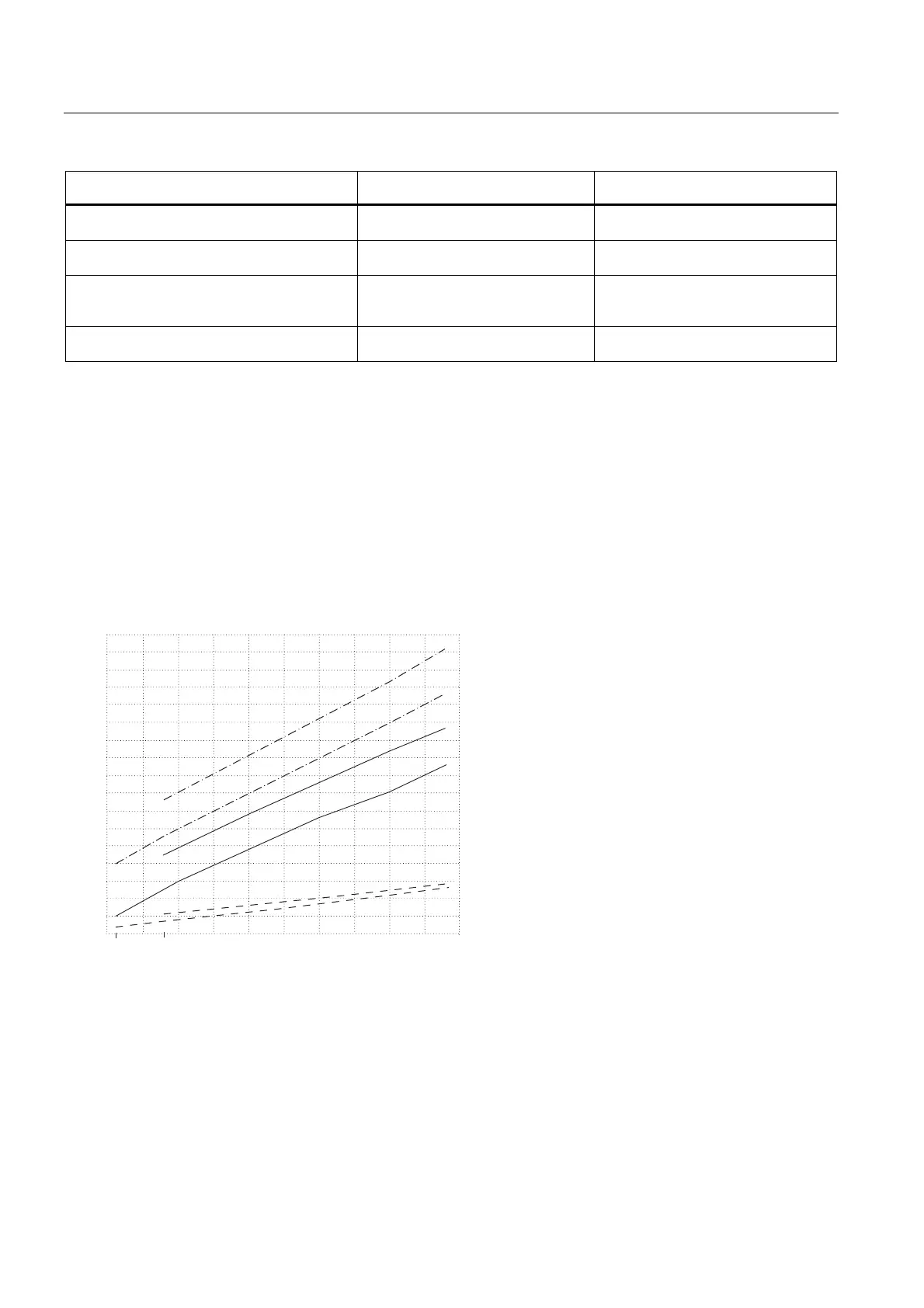
The lower graphic shows that the OB1 cycle is influenced by increasing the cyclical
PROFINET interconnections to remote partners at PROFINET:
&382%F\FOHZLWKUHPRWH352),1(7SDUWQHUV
'HSHQGHQF\RIWKH2%F\FOHRQWKHXPEHURILQWHUFRQQHFWLRQV
&\FOHWLPHLQ˩V
1XPEHURIF\FOLFDO&%$LQWHUFRQQHFWLRQV
&382%F\FOHZLWKUHPRWH352),1(7SDUWQHUV
&382%F\FOHZLWKUHPRWH352),1(7SDUWQHUV
&382%F\FOHZLWKUHPRWH352),1(7SDUWQHUV
&382%F\FOHZLWKUHPRWH352),1(7SDUWQHUV
&382%F\FOHZLWKUHPRWH352),1(7SDUWQHUV
Base load through PROFIBUS devices
The 16 PROFIBUS devices with their interconnections among each other generate an
additional base load of up to 1,0 ms.
 Loading...


