C7-Ein-/Ausgabebaugruppe / C7 Input/Output Module
32
Produktinformation
/ Product Information
C79000-Z7074-C630-01
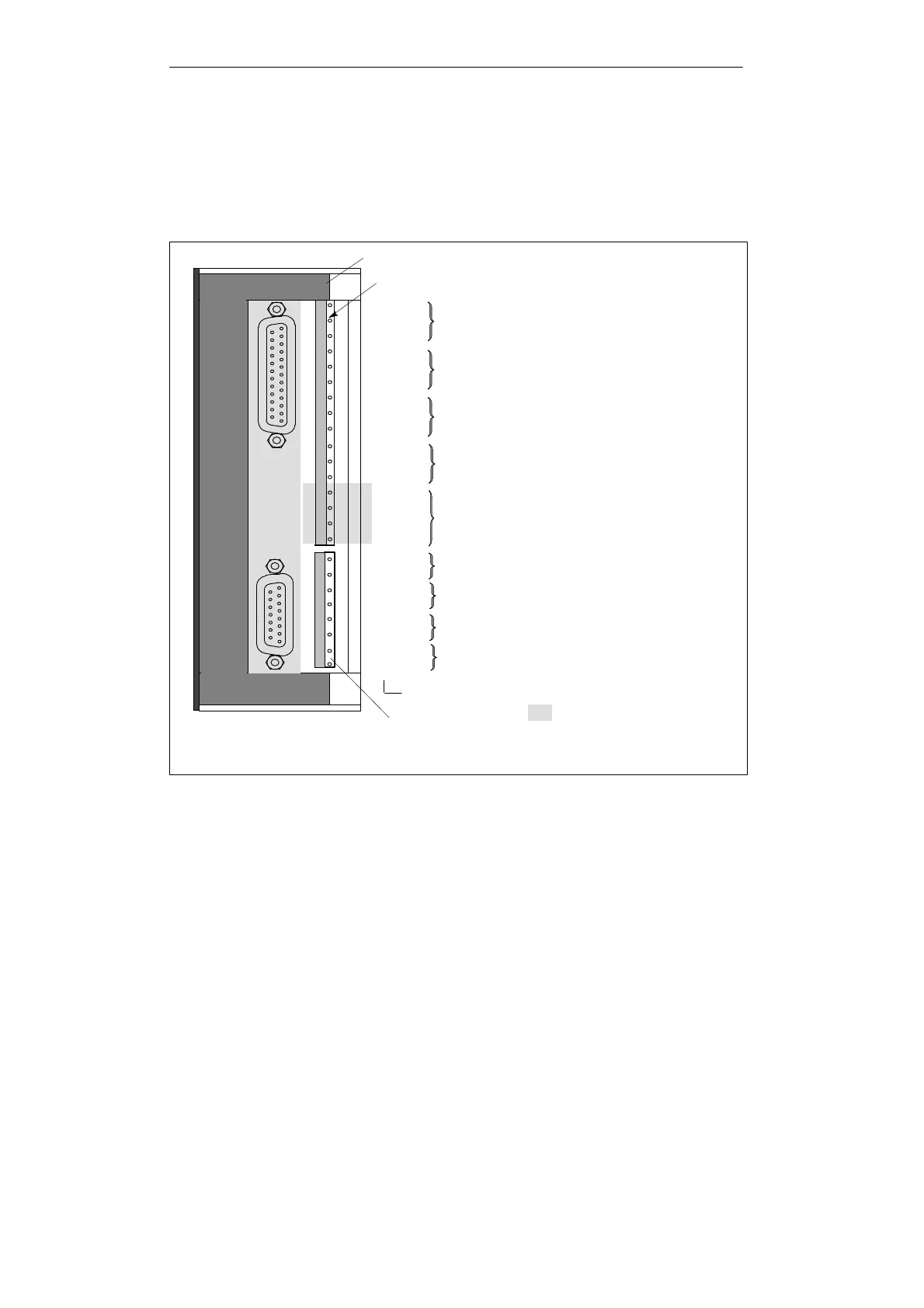
4.6.3 Pinout and Addressing of the Analog I/Os
An analog channel is always addressed word by word.
Figure 1-16 shows which channel addresses are obtained. You will see that, in the
case
of the analog I/Os, the analog input channels and the analog output channel are
addressed as of the same address, the start address.
M
ANA
AO1
AO2
AO3
AO4
M
ANA
M
ANA
M
ANA
Channel 0: Address PQW 304*; PQW 272**
Channel 1: Address PQW 306*; PQW 274**
Channel 2: Address PQW 308*; PQW 276**
Channel 3: Address PQW 310*; PQW 278**
Analog inputs
Channel 0: Address PIW 304*; PIW 272**
Channel 1: Address PIW 306*; PIW 274**
Channel 2: Address PIW 308*; PIW 276**
Channel 3: Address PIW 310*; PIW 278**
Not occupied
Inputs with this shading
have no relevance to this
example
AI1-U
AI1-I
AI1-M
AI2-U
AI2-I
AI2-M
AI3-U
AI3-I
AI3-M
AI4-U
AI4-I
AI4-M
V
iew of right side
Analog outputs
Pin designations
*
Connection to C7-6xx/P
**
Connection to C7-63x DP
Bild 1-16 Addresses of the Analog Inputs and Outputs in the Case of Connection to the
C7-6xx/P or C7-63x DP
Addresses
of the
Analog Func
-
tions
 Loading...