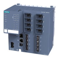
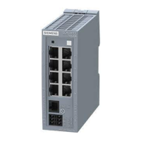
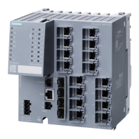
Figure 4-1 DIN rail mounting with securing bar in the wall mounting position.
Securing bar in the wall mounting position (as supplied).
To install the device on a 35 mm DIN rail complying with DIN EN 60715, follow the steps below:
1. Loosen the knurled screw with your hand or a screwdriver.
2. Place the third housing guide of the device on the top edge of the DIN rail.
3. Press the device down against the DIN rail until the spring securing bar locks in place.
4. When you tighten the knurled screw. you cannot release the securing bar (torque 0.5 Nm).
The device is additionally fixed.
5. Connect the electrical connecting cables, refer to the section "Connecting up (Page 49)".
Removal
To remove the device from a DIN rail, follow the steps below:
1. Disconnect all connected cables.
2. If necessary, loosen the knurled screw with your hand or a screwdriver.
3. Lever the securing bar down using a screwdriver as far as it will go.
4. Pull the device away from the bottom of the DIN rail with the bar pulled.
4.4 Installation on a standard S7-300 rail
Installing on an S7-300 standard rail
Note
Note the position of the securing bar, see also section “Dimension drawings SCALANCE
XC-200 (Page 69)“.
When supplied, the securing bar is in the wall mounting position. To change the position of the
securing bar, refer to the section “Changing the position of the securing bar (Page 46)“.
Mounting
4.4 Installation on a standard S7-300 rail
SCALANCE XC-200
42 Operating Instructions, 12/2017, C79000-G8976-C442-03
 Loading...


