Technical description
3-6 SIMODRIVE base line A Start-Up
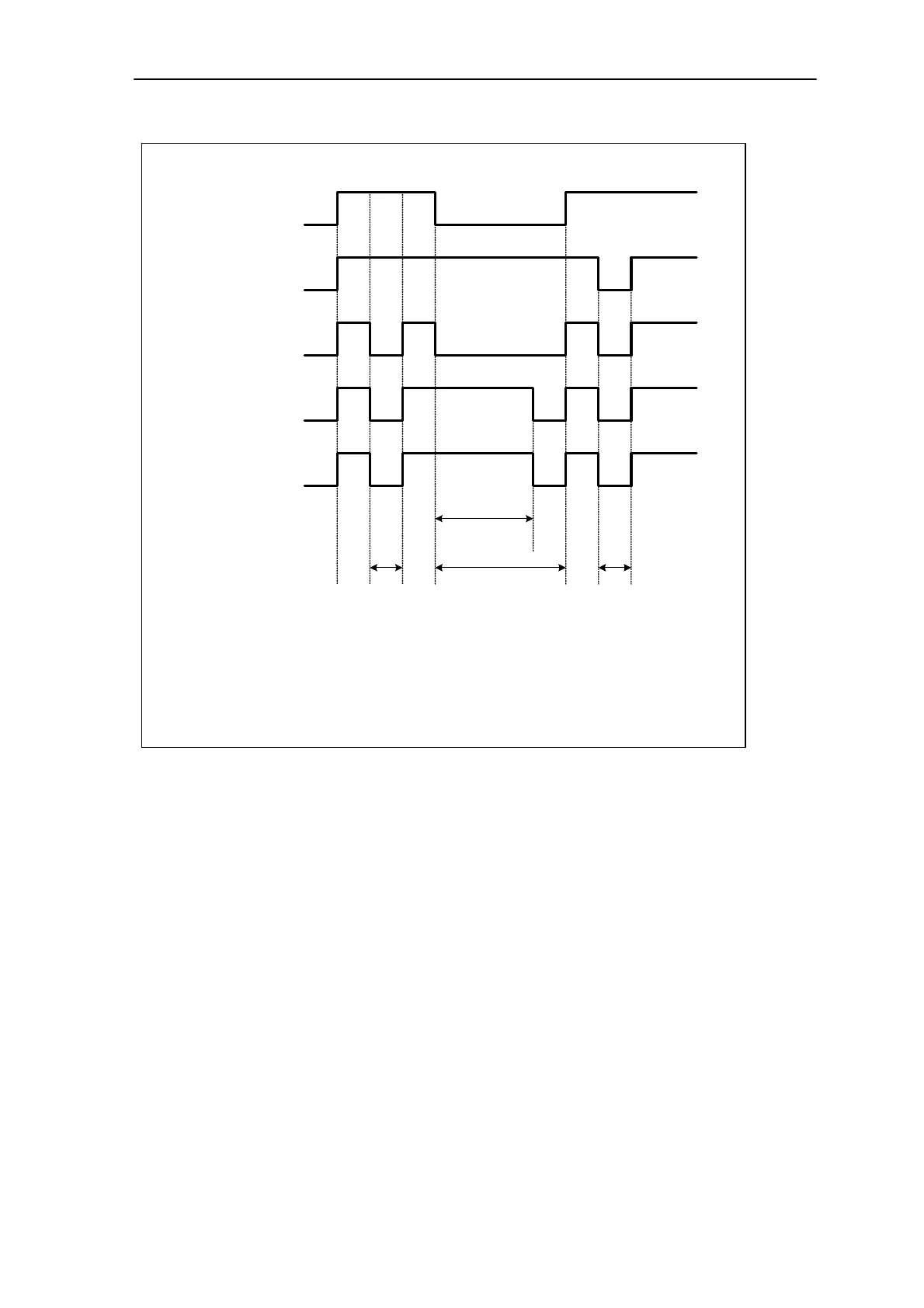
Enable signal The time diagram of enable signals in control module is shown in Fig.3-5.
12
240ms
Axis inhibit
terminal 65.1
Axis inhibit
terminal 65.2
Speed setpoint
inhibit
Output pulse
inhibit
Internal enable
inhibit
3
Note:
1.Terminal 65.1 is inhibited. Feed modules are inhibited.Speed setpoint is set
to 0. After the set timers have expired (as supplied:240ms), all of the
controllers are inhibited.
2. Terminal 65.2 is inhibited.Feed modules are inhibited immediately. The drives
coast down unbraked.
Fig.3-5 Enable signal in control module
Monitoring function Heatsink overtemperature / I
2
t monitoring
● Heatsink overtemperature monitoring:
when the heatsink shutdown temperature is reached, the fault signal is
output. And the axes are stopped.
● I
2
t monitoring:
when the limiting becomes active, the fault signal is output. And the
axes are stopped.
Motor overtemperature
● SIMODRIVE base line A feed modules with closed-loop control for
servomotors are equipped with an evaluation circuit for the PTC
thermistors integrated in the motor windings. The monitoring
combination is intended to protect the motors against inadmissible
high winding temperatures (trip temperature 150°C).

 Loading...


