Servomotor
SIMODRIVE base line A Start-Up 4-3
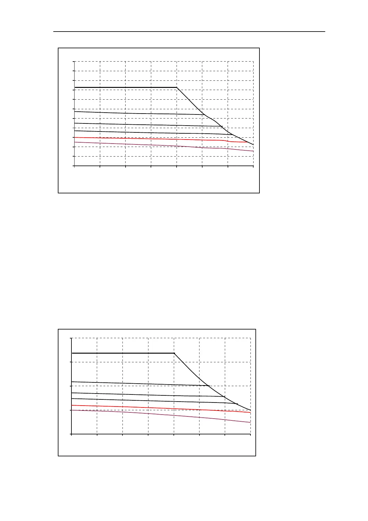
1FK7042 - 5AF71
0
1
2
3
4
5
6
7
8
9
10
11
0 500 1000 1500 2000 2500 3000 3500
Speed
[min-1]
Torque
[Nm]
S1 (100K)
S1 (60K)
S3 - 25%
S3 - 40%
S3 - 60%
Fig. 4-1 Motor speed – torque diagram 1FK7042-5AF71-1S□0
Remarks in the above graphics (valid for the sequent figures):
S1 (60K): torque output during continous operation at temperature rise of 60K;
S1 (100K): torque output during continous operation at temperature rise of 100K;
S3 –60%: load cycle in case of intermittent periodic duty, 60% means the ratio of working time
with constant load to the whole cycle;
S3 –40%: load cycle in case of intermittent periodic duty, 40% means the ratio of working time
with constant load to the whole cycle;
S3 –25%: load cycle in case of intermittent periodic duty, 25% means the ratio of working time
with constant load to the whole cycle;
Max.torque curve: it is the characteristics curve of max. torque, which can not be exceeded.
[a] MASTERDRIVES MC:V
DC link
=540V(DC)、V
motor
=340Vrms
1FK7060 - 5AF71
0
5
10
15
20
0 500 1000 1500 2000 2500 3000 3500
Speed [min-1]
Torque [Nm]
S1 (100K)
S1 (60K)
S3 - 25%
S3 - 40%
S3 - 60%
Fig. 4-2 Motor speed – torque diagram 1FK7060-5AF71-1 S□0

 Loading...


