Page 20 Version 1.0 March 1, 2000
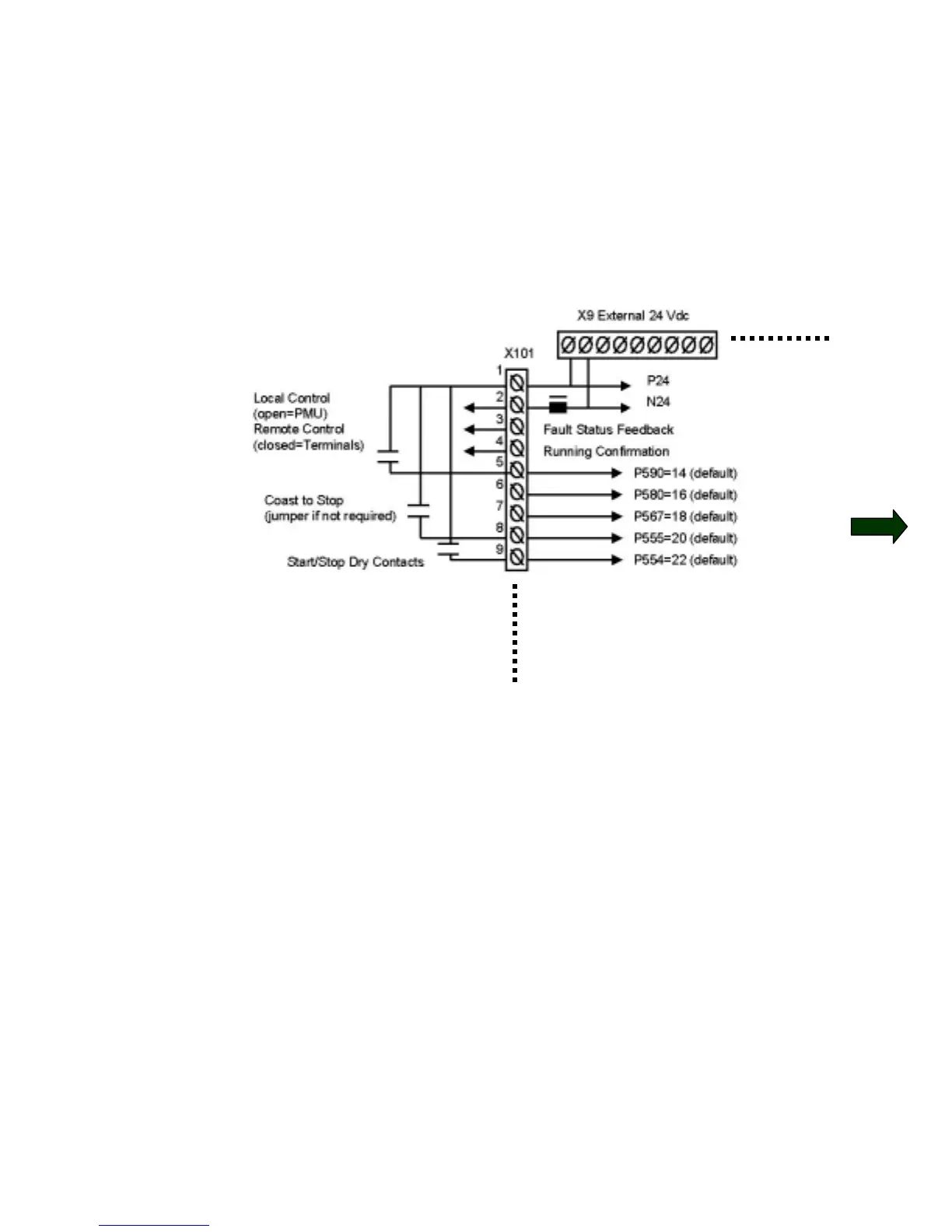
Connect External Wiring as connection diagram.
Step 1: Dry set of contacts between terminals X101, pin#1 and pin#5 for
Local/Remote Mode Selection. Jumper if not required.
Step 2: Dry set of contacts between terminals X101, pin#1 and pin#8 for
Coast to Stop Selection. Jumper if not required.
Step 3: Dry set of contacts between terminals X101, pin#1 and pin#9 for
Source of Main Start/Stop Selection.
Step 4: Dry set of contacts between terminals X101, pin#1 and pin#7 for
Source of Fault Reset. Leave open if not required. “P” button on PMU
will be fault reset location if pin#7 is not used.
Step 5: Dry set of contacts between terminals X101, pin#1 and pin#6 for
Fixed Speed or Preset Speed Selection. Leave open if not required.
Internal Connections
Custome
Connection Points
 Loading...


