Version 1.0 March 1, 2000 Page 29
1.4 Drive Control Word
Function Diagrams will be referred to in brackets with their number. Please refer to
function diagrams in the compendium. Example [Diagram Number]
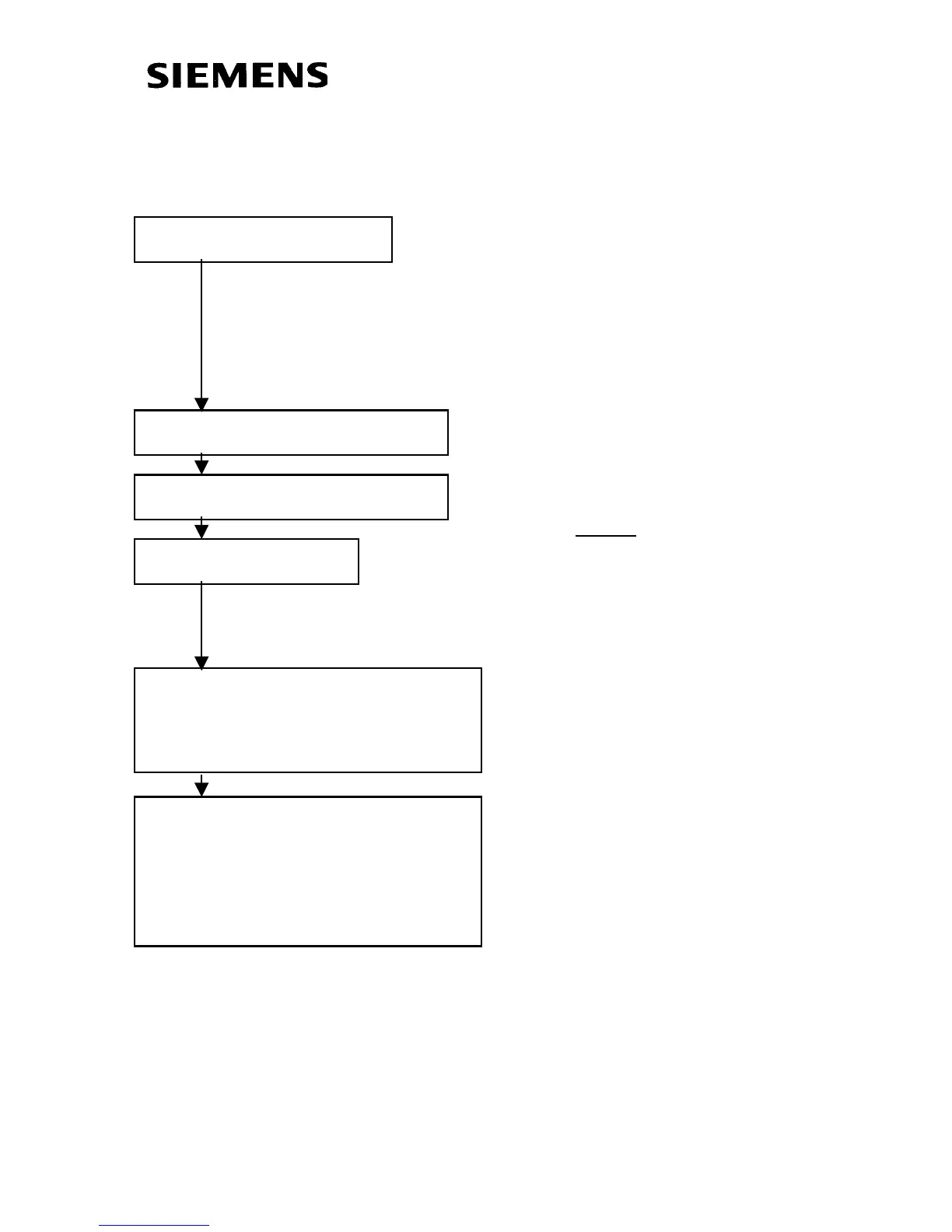
Assign Digital Inputs
Assign Off2(Coast Stop)
Assign Off3(Quick Stop)
Assign ON/OFF1
[180] Assign Other
Functionality as
Required
See [190]
Assign Other Control
Functionality as
Required
Digital Inputs/Outputs:
Binector Assignments for Control
may be made from Digital Inputs
P555, P556 & P557 can be used
to assign Coast to Stop
P558, P559 & P560 can be used
to assign Quick Stop
P554 MUST be assigned to
activate drive. Note:
Acceleration and Deceleration
will be based on ramp generator
[320]
 Loading...


