page 7808D turning and milling Service guide
车削与铣削
车削与铣削车削与铣削
车削与铣削 第
第第
第页
页页
页 服务指南
服务指南服务指南
服务指南
硬件故障
硬件故障硬件故障
硬件故障
服务案例
服务案例服务案例
服务案例
故障现象描述
故障现象描述故障现象描述
故障现象描述:
上电后无法进入系统,常见现象为出现黑屏无任何显示。
诊断步骤
检查 面板上的“电源”指示灯是否点亮
开机不能
开机不能开机不能
开机不能
进入系统
进入系统进入系统
进入系统
如果指示灯亮
断电检查 卡是否插
紧,重新上电开机,观察
故障是否解除。
如果指示灯不亮
检查 PPU 后侧 X1 电源插头接口
1. 接线是否松动
2. 24v 端子是否与接口相符
3. 用万用表测量是否有 DC24V
故障现象描述
故障现象描述故障现象描述
故障现象描述:
系统出现电池报警
诊断步骤
电池报警
电池报警电池报警
电池报警
系统出现电池报警时,说明系统电池电
量不足,需要更换电池。
请在系统上电状态下将电池拔出,进行
电池更换!
如果上述检查之后故障仍然存在,则很可能是系统主板 () 损坏,需要
进行更换或维修
电池报警号为 002100:此报警表明系统电池电量已经不足,应在出现该
报警的 6 周之内更换电池,否则可能会导致数据丢失。
电池报警号为 002101:此报警表明系统电池电量即将用尽,需立即更换
电池,否则可能会导致数据丢失。
Startup
cannot
log into the
system
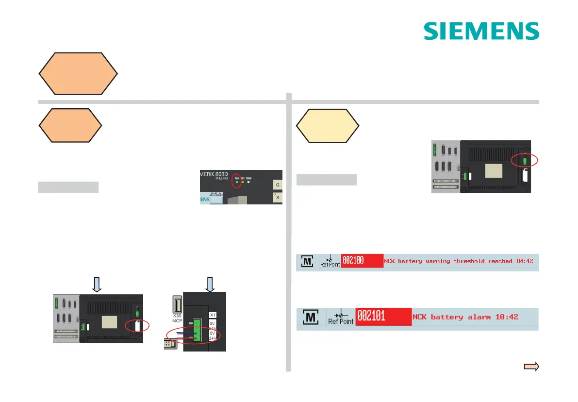
Battery
alarm
Fault description:
Cannot log into the system after power on; normally black screen, no
display at all.
Fault description:
The system issues a battery alarm.
Check the power indicator light on the PPU panel:
Replacement and maintenance are necessary if the fault still exists after
the above inspection, because it is probable that the PPU is damaged.
Battery alarm number 002100: This alarm indicates that the battery
power of the system is l
ow. In this case, replace the battery within six
weeks, otherwise it may cause data loss.
Battery alarm number 002101: This alarm indicates that the battery
power of the system will soon be used up. In this case, replace the battery
immediately, otherwise it may cause data loss.
If the indicator light is off:
Check the X1 power plug interface on
the back of the PPU
1. Whether the connection is loose.
2. W
hether the 24 V terminal matches
the interface.
3. Whether 24 VDC is available by
measuring with a multi- meter.
If the indicator light is on:
Power off and check whether
the CF card is inserted correctly,
then power on and
restart, observe whether the
fault is eliminated.
Service case
of hardware
fault
Diagnostic steps
Diagnostic steps
Replace the battery when the system
issues the alarm
“
shortage of electricity
”
.
Remove the battery and replace it in
the power-on sta
te.

 Loading...


