808D Page 39 Operating and Programming — Milling
Create Part
Program
Part 2
s
Content
Basic Theory
Unit Description
This unit describes how to create a part program, edit the part program
and get to know the most important CNC commands required to produce
a workpiece.
Part 2
Unit Content
Radius and
chamfers
Tapping
Hole
centering
Drilling
holes
Hole
positioning
Contour
milling with
cycle
Milling slots
and spigots
Radius and
chamfers
N55 SUPA G00 Z300 D0
N60 SUPA G00 X300 Y300
N65 T3 D1
N70 MSG("Please change to Tool No 3")
N75 M05 M09 M00
N80 S5000 M3 G94 F300
N85 G00 X-6 Y92
N90 G00 Z2
N95 G01 F300 Z-10
N100 G41 Y 90
N102 G01 X 5
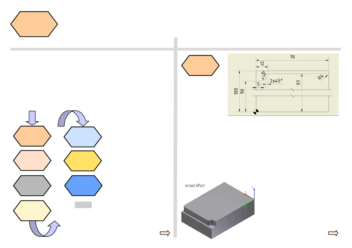
N105 G01 X12 RND=5
N110 G01 Y97 CHR=2
N115 G01 X70 RND=4
N120 G01 Y90
N125 G01 G40 X80
N130 G00 Z50
The two radii and
the chamfer shown
in the diagram can
be produced with
the code marked in
the program below.
RND = Radii
CHR = Chamfer
(specified side length of isosceles
triangle with chamfer as base
line)
CHF=Chamfer
(specified base line length of
isosceles triangle with chamfer as
base line)
End

 Loading...


