Parameter Description
FZ (only for G code) Depth infeed rate *
Machining The following machining operations can be selected:
● ∇ (roughing)
● ∇∇∇ (finishing)
● Chamfering
X0
Y0
Z0
The positions refer to the reference point:
Reference point X – (single position only)
Reference point Y – (single position only)
Reference point Z – (only single position and G Code position pattern)
mm
mm
mm
W Width of spigot mm
L Length of spigot mm
R Corner radius mm
Z1 Depth referred to Z0 (inc) or spigot depth (abs) - (only for ∇ and ∇∇∇ edge) mm
DZ Maximum depth infeed – (only for ∇ and ∇∇∇) mm
UXY Plane finishing allowance for the length (L) and width (W) of the rectangular spigot.
Smaller rectangular spigot dimensions are obtained by calling the cycle again and pro‐
gramming it with a lower finishing allowance. - (only for ∇ and ∇∇∇).
mm
UZ Depth finishing allowance (tool axis) – (only for ∇ or ∇∇∇) mm
W1 Width of blank spigot (important for determining approach position) - (only for ∇ and
∇∇∇)
mm
L1 Length of blank spigot (important for determining approach position) - (only for ∇ and
∇∇∇)
mm
FS Chamfer width for chamfering - (for chamfering only) mm
ZFS Insertion depth of tool tip (abs or inc) - (for chamfering only) mm
* Unit of feedrate as programmed before the cycle call
Hidden parameters
The following parameters are hidden. They are pre-assigned fixed values or values that can
be adjusted using setting data.
Parameter Description Value Can be set in SD
PL (only for G code) Machining plane Defined in MD
52005
SC (only for G
code)
Safety clearance 1 mm x
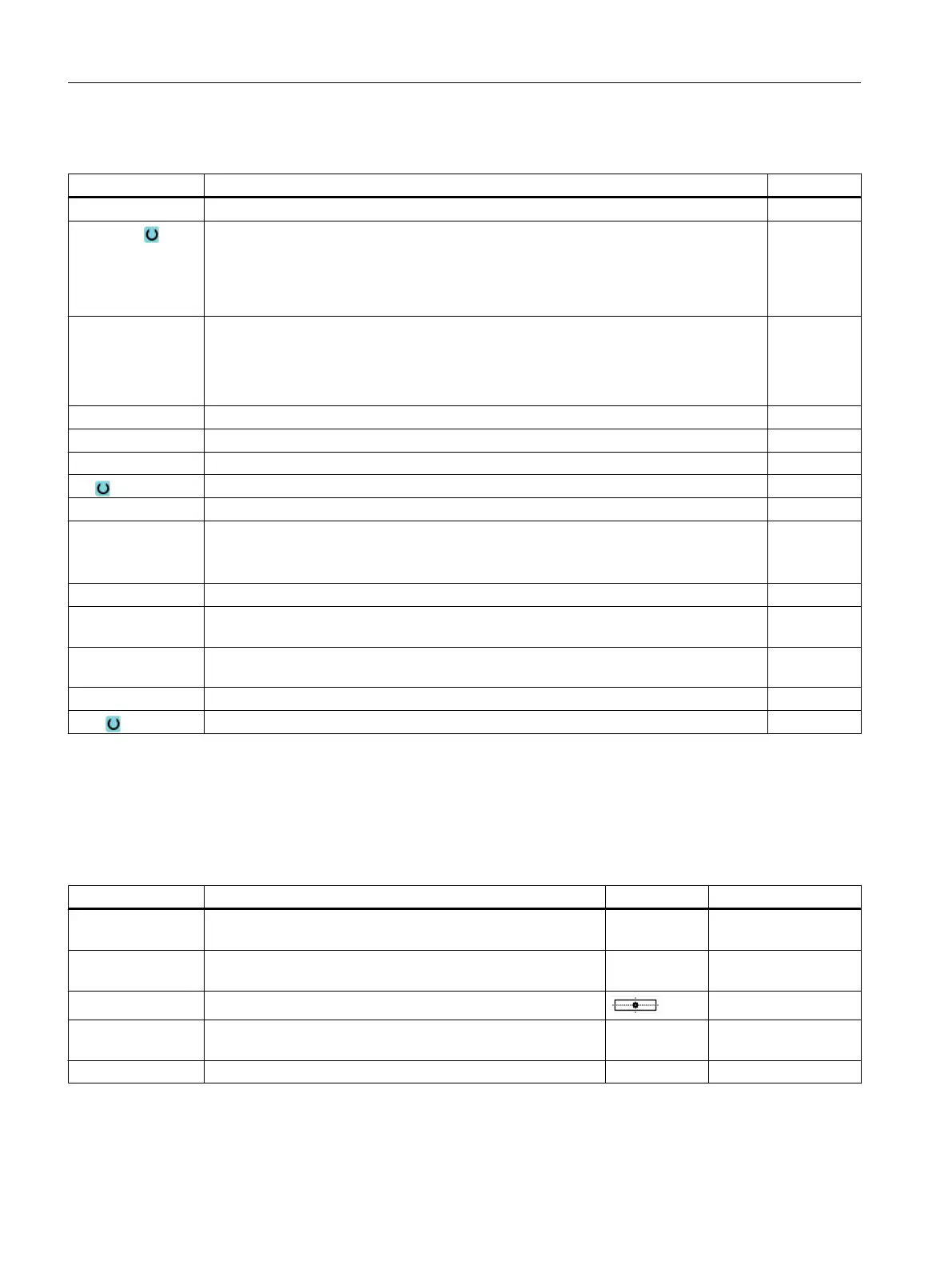
Reference point Position of the reference point: Center
Machining
position
Mill rectangular spigot at the programmed position (X0, Y0,
Z0).
Single posi‐
tion
α0 Angle of rotation 0°
Programming technological functions (cycles)
10.2 Milling
Milling
440 Operating Manual, 08/2018, 6FC5398-7CP41-0BA0
 Loading...


