Operator control and display elements
5
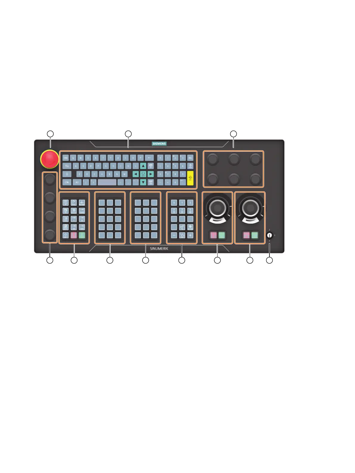
5.1 Front side
Overview
① Emergency stop button
② QWERTY keyboard
③ 6x mounting space for 22.5mm elements
④ Key-operated authorization switch
⑤ Powerride 1 (feed) + keypad 4.1
⑥ Powerride 2 (spindle) + keypad 4.2
⑦ Keypad 4 (axis block)
⑧ Keypad 3 (customer keys)
⑨ Keypad 2 (customer keys)
⑩ Keypad 1 (operating mode block)
⑪ 4x mounting space for 22.5mm elements
Figure5-1 Position of operator controls on the MCP 2400
Labeling of the keys
The keys are designed with replaceable caps for machine-specic adaptations. The key caps can
be freely inscribed using a laser. Alternatively, you can use transparent key caps and insert labels.
ONE MCP Part 2: MCP 2400
Equipment Manual, 08/2023, A5E50324707B AB 19

 Loading...