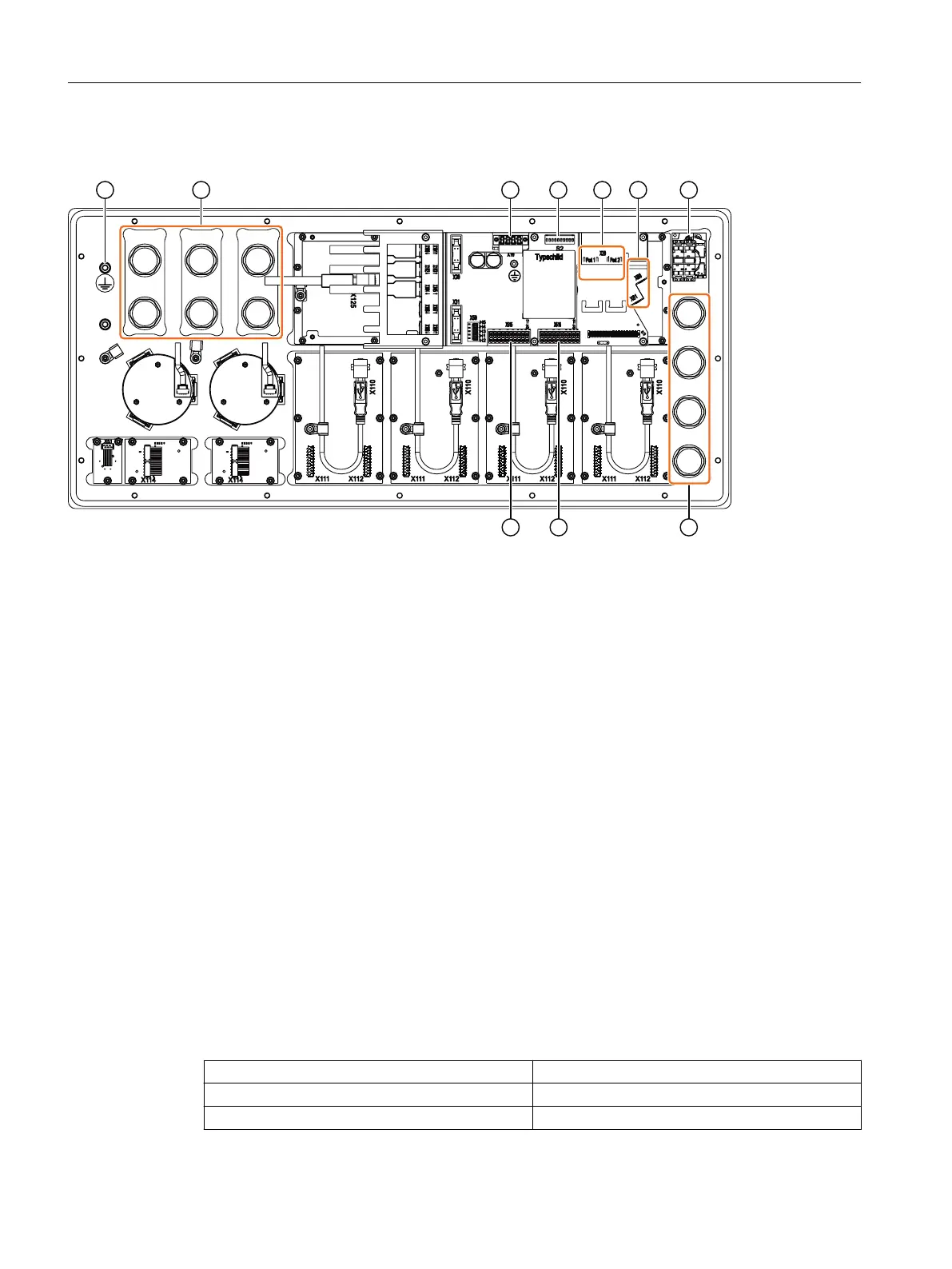
5.2 Rear side
① Protective conductor connection
② 6x mounting space for 22.5mm elements
③ Power supply interface X10
④ Switch S2
⑤ Ethernet interfaces X20 port 1/ port 2
⑥ Handwheel connections X60/ X61
⑦ Emergency stop
⑧ 4x mounting space for 22.5mm elements
⑨ Interface of the customer-specic inputs/outputs X516
⑩ Interface of the customer-specic inputs/outputs X515
Figure5-2 Rear view of the MCP 2400
Handwheel connecting cable
The handwheel connecting cable is not included in the scope of delivery. You will nd the article
numbers in Chapter "Spare parts/accessories".
5.3 Conguration
Input image
Slot 1 Base
Slot 2 Keypad 1 (operating mode block)
Slot 3 Keypad 2 (customer keys)
Operator control and display elements
5.3Conguration
ONE MCP Part 2: MCP 2400
20 Equipment Manual, 08/2023, A5E50324707B AB

 Loading...