Preparing for Operation
35
SIP ART PS2 Manual
A5E00074631-01
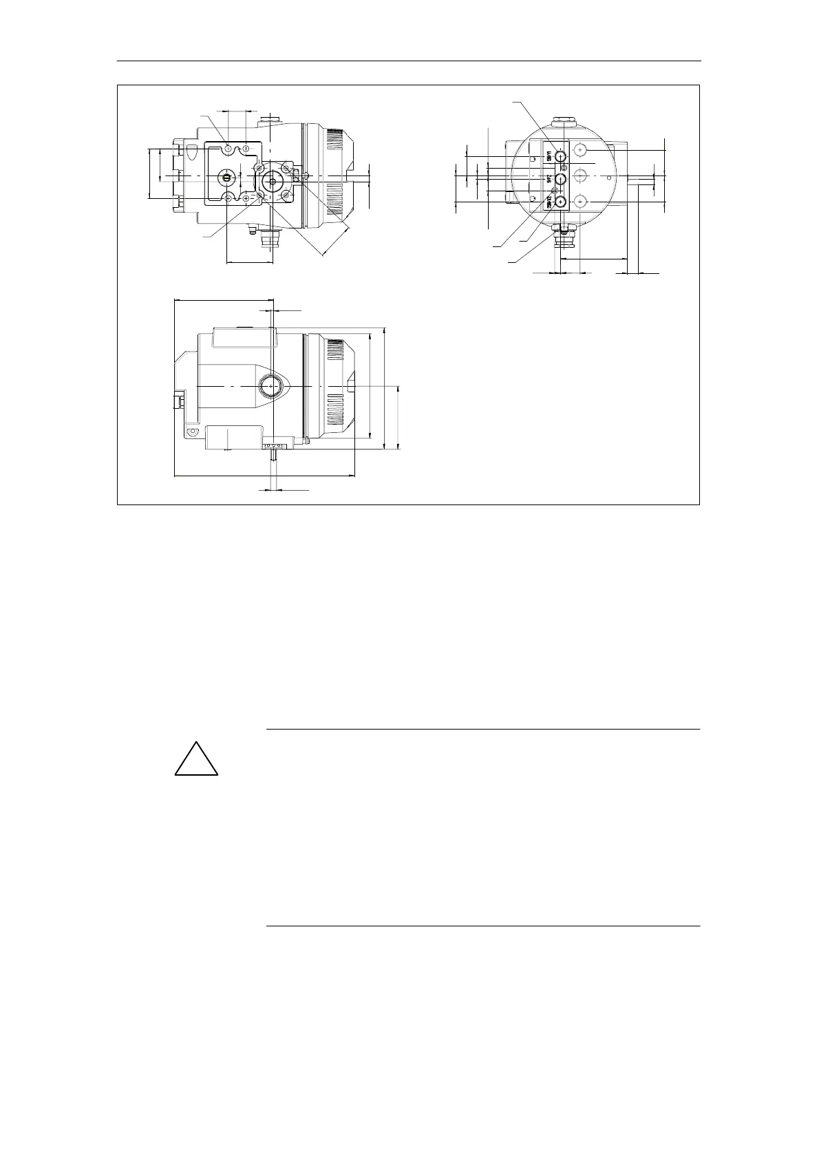
M8, 14 deep (4x)
23
129,5
Æ 8h9
3,5
235,3
60
M6, 11 deep (4x)
All air connections
G
1/
4
or
1
/
4
”NPT
7,5
25,7
14,3
1)
M6, 8 deep (2x)
M20, M25 or
1/
2
”NPT (2x )
87,2
65
43
7,75
50
Æ
Æ 136.5
34
25
4,5
10,25
19,25
33,5
33,5
7
12
E
82,5
158,5
1)
Connection 238/Y2 only in
double action version
Figure 3-4 Dimensional drawing for positioner with metal housing in explosion proof
version 6DR5xx5
3.3 Assembly
!
W ARNING
To avoid injury or mechanical damage to the positioner/mounting kit,
the following order must be observed for assembly:
1. Mechanical fitting of positioner this chapter
2. Connection of electric power supply see chapter 3.4, p. 48
3. Connection of pneumatic power supply see chapter 3.5, p. 56
4. Put into operation see chapter 3.6, p. 57
Please also observe the warning on page 48!
General
 Loading...