10 SIPROTEC 4/5, Injection Unit 7XT71, Product Information
C53000-B1174-C128-7, Edition 09.2016
6.2 Injection Unit 7XT7100-0BA00 for Panel Surface
Mounting
The plug-in module is inserted into the sheet-metal housing and fastened with
2 screws. A Z angle for panel surface mounting is fastened to the upper and lower
section of the front cover. When delivered from the factory, the Z angles are not yet
screwed on.
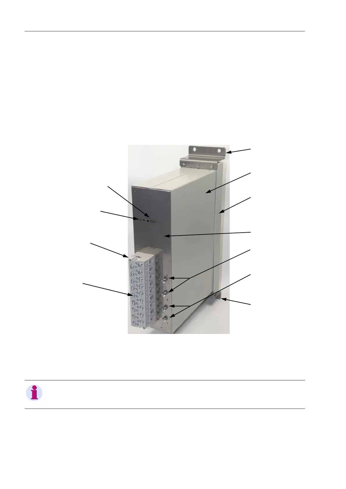
The rear plate accommodates the terminal strip with 18 screw terminals for external
cabling, 2 LEDs (RUN, ERROR) for signaling the device status and the grounding
connections.
Fig. 6-1 Injection Unit 7XT7100-0BA00 for Panel Surface Mounting
In each screw terminal you can screw up to 2 ring-type or fork-type cable lugs on
2 copper cables. Chapter 8 lists the size of the ring-type or fork-type cable lugs and
the possible maximum conductor diameters.
Figure 7-1 depicts the housing dimensions.
Rear plate
Z angle
Z angle
Housing
Front cover
LED RUN
LED ERROR
Terminal strip
Screw terminals
Protective
Shielding
connections
connections
conductor
NOTE
The 2 LEDs on the front cover and on the rear plate have the same functions.
 Loading...