11SIPROTEC 4/5, Injection Unit 7XT71, Product Information
C53000-B1174-C128-7, Edition 09.2016
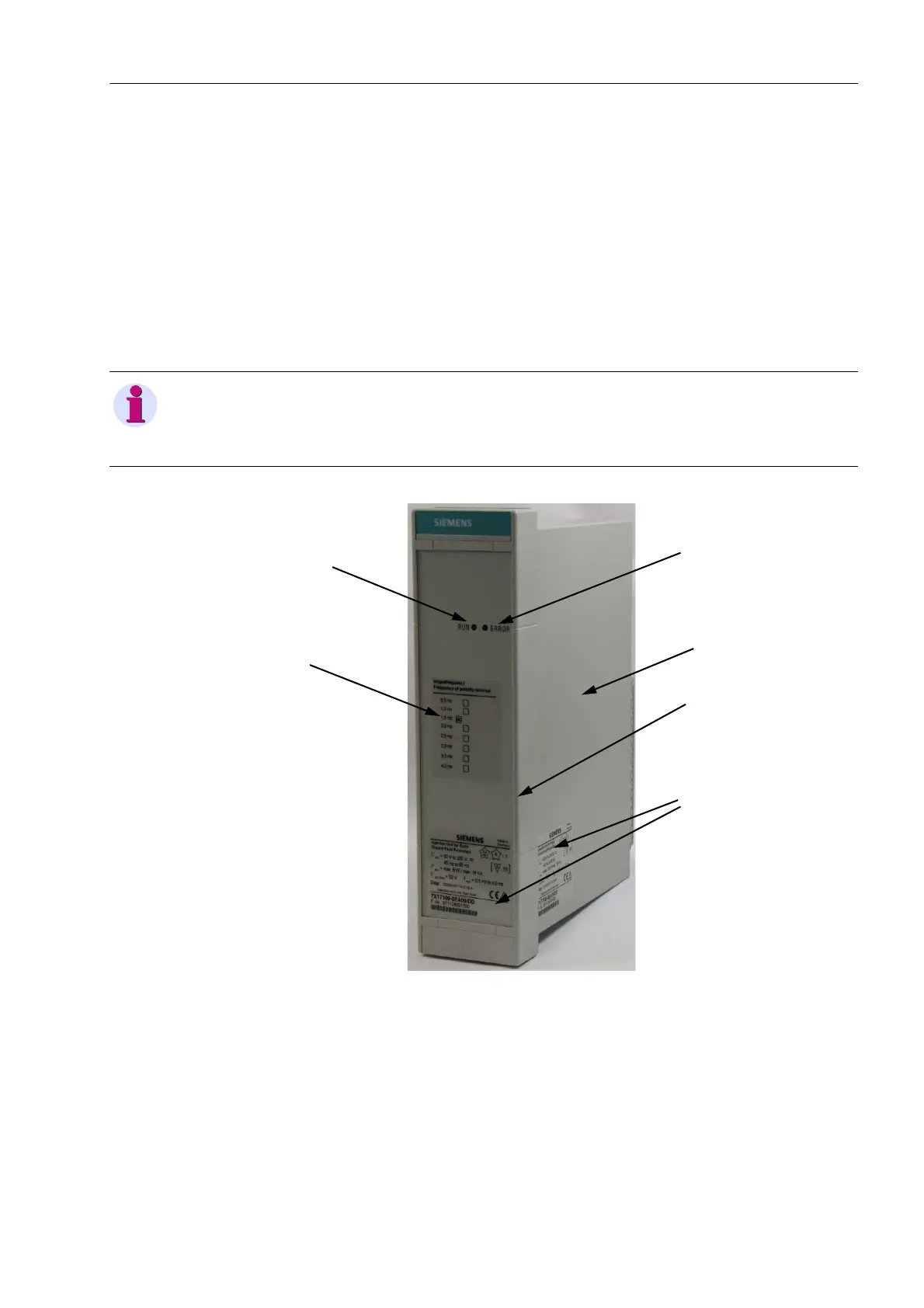
6.3 Injection Unit 7XT7100-0EA00 for Panel Flush
Mounting or Cubicle Installation
The plug-in module is inserted into the sheet-metal housing and fastened with
2 screws.
2 LEDs (RUN, ERROR) on the upper section of the front cover signal the device
status.
The rear plate accommodates the terminal strip with 18 screw terminals for external
cabling and the grounding connections (see figure 6-1).
Fig. 6-2 Injection Unit 7XT7100-0EA00 for Panel Flush Mounting or Cubicle In-
stallation
In each screw terminal you can screw up to 2 ring-type or fork-type cable lugs or up
to 2 copper cables. Chapter 8 lists the size of the ring-type or fork-type cable lugs
and the possible maximum conductor diameters.
Figure 7-2 depicts the housing dimensions.
NOTE
The 2 LEDs on the front cover and on the rear plate of the device have the same
functions.
LED RUN
LED ERROR
Housing
Front cover
Name plate
Option plate
 Loading...