20 SIPROTEC 4/5, Injection Unit 7XT71, Product Information
C53000-B1174-C128-7, Edition 09.2016
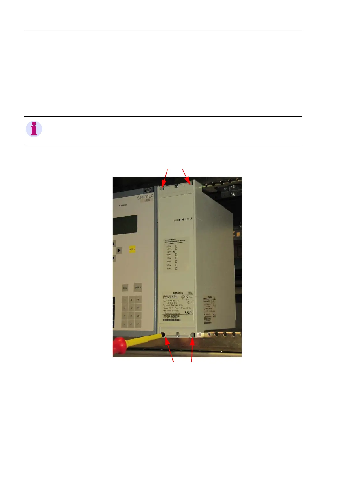
8.3 Panel Flush Mounting or Cubicle Installation
(7XT7100-0EA00)
✧ Remove the 2 cover caps on the front cover upward and downward,
respectively (see figure 8-1).
✧ Push the device either into the opening of the switch panel or into the control
cabinet, depending on the application.
✧ Use 4 screws to fasten the device to the switch panel or in the control cabinet.
Fig. 8-3 Installing the Device into the Switch Panel
✧ Push the 2 cover caps back into the front cover (see figure 8-1).
✧ Wire the device as described in Chapter 8.4.
The terminal strip is accessible from behind for this type of assembly.
NOTE
Observe the dimensions and notes in Chapter 7.1.
 Loading...