24 SIPROTEC 4/5, Injection Unit 7XT71, Product Information
C53000-B1174-C128-7, Edition 09.2016
9.2.2 Removing and Installing the Plug-in Module
Removing and Installing the Plug-in Module of the Injection Unit in the Surface-mount-
ing Housing 7XT7100-0BA00
✧ Switch off the device that supplies the auxiliary voltage to the
Injection Unit 7XT71.
✧ Switch off all voltages that supply the device.
✧ Release and remove the 2 screws at the lower and upper Z angle that fasten
the device to the switch panel.
✧ Detach the device from the switch panel.
✧ Release the 4 screws that fasten the Z angle to the housing and remove the
Z angles (see figure 8-2).
✧ Remove the 2 cover caps on the front cover upward and downward,
respectively (see figure 8-1).
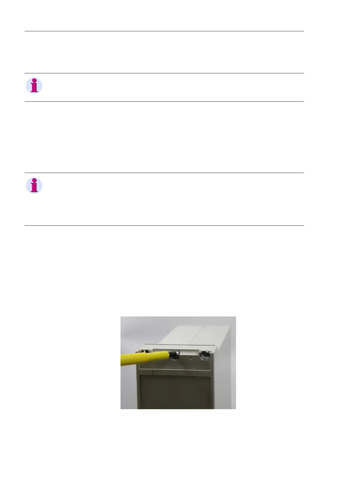
✧ Unscrew and remove the center screws on the upper and lower front cover.
Fig. 9-1 Layout of the Front Cover
NOTE
Observe the notes on electrostatic sensitive devices in Chapter 9.1.
NOTE
The cables connected to the terminal strip do not necessarily have to be discon-
nected from the device. Only disconnect the cables from the terminal screws if
there is insufficient installation clearance for the steps described in the following.
Observe the safety notes in Chapter 8.4.
 Loading...