2 Functions
256
7UT613/63x Manual
C53000-G1176-C160-2
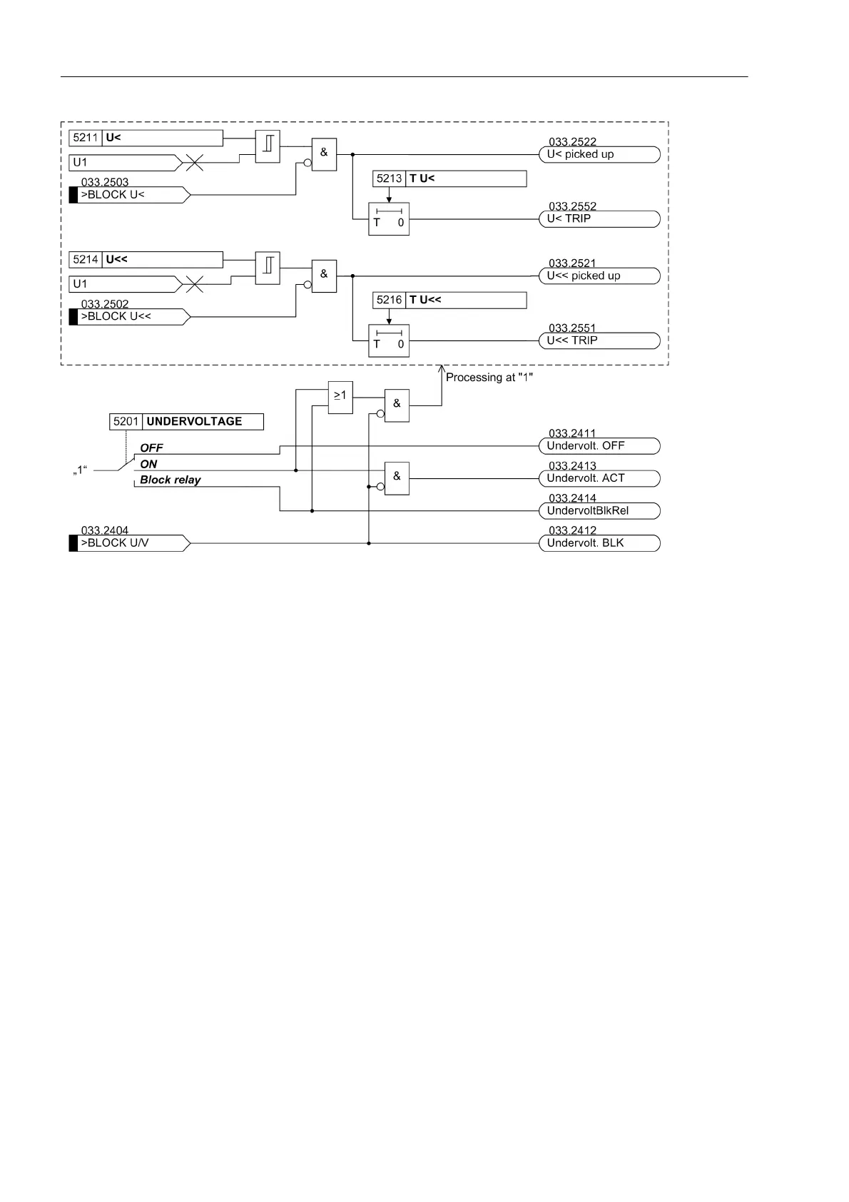
Figure 2-104 Logic diagram of the undervoltage protection
2.14.2 Setting Notes
General The application of undervoltage protection is only possible in 3-phase protected ob-
jects. Furthermore, it is a prerequisite that the device is connected to a three-phase
voltage transformer set.
Undervoltage protection is only effective and accessible if address 152 was set to
UNDERVOLTAGE Enabledduring configuration of the protection function (section
2.1.3).
Under address 5201 UNDERVOLTAGE the undervoltage protection ON or OFF can be
set. Additionally, the command can be blocked if the protection function is enabled
(Block relay).
Pickup Values,
Times
The undervoltage protection consists of two phases. The equivalent of the phase-
phase voltage is detected, therefore √3·U
1
. The setting is thus effected in interlinked
values.
The U< stage is set slightly below the minimum operational expected voltage under
address 5212 U<, if the reference values are relevant, under address 5211 U< when
setting in volts. This setting method depends on whether the voltage transformer set
has been assigned to one side of the main protected object or to any measuring loca-
tion. Normally, 75 % to 80 % of the nominal voltage is recommended; i.e. 0.75 to 0.80
for reference values or 75 V to 80 V for U
Nsec
= 100 V (adjusted accordingly in case
of different nominal voltage).

 Loading...


