Description, device design, dimension drawing
2.2 Connections and terminal designation
SITOP SEL1200-1400
Manual, 06.2019, A5E46496083-1-76
11
2.2 Connections and terminal designation
The input terminals ① can be used to establish the connection to the supply voltage. The
"0 V" connection
② is used to supply the internal electronics. The output terminals ③ are
used to connect to the loads to be supplied (see also Chapter Installation (Page 33)).
The operating state of the device can be processed using the group signal contact
④ (for
the function and content rating, see Figure 2-4 Status displays and signaling (Page 13)).
The remote reset (RST) input
④ is used to reset outputs that have automatically been shut
down (function, see Chapter Status displays and signaling (Page 13)).
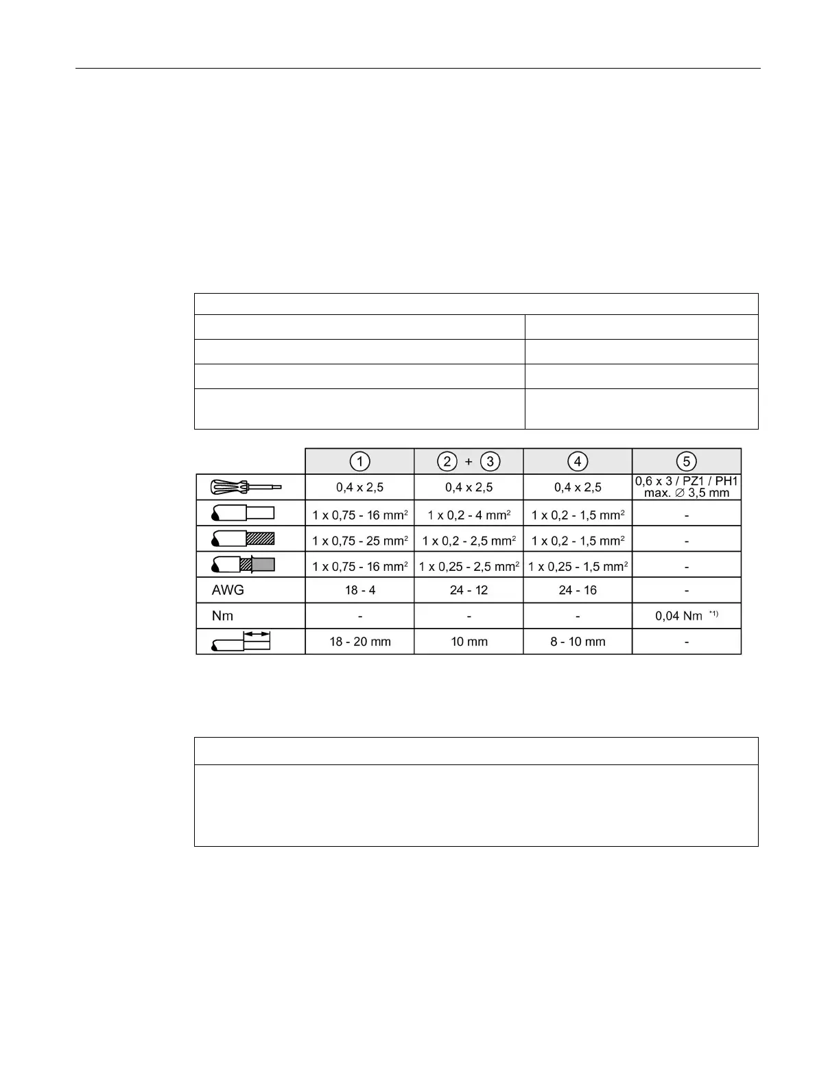
Connections and terminal designations
24 V DC input
2 spring-loaded terminals
0 V connection for the internal supply
2 spring-loaded terminals
24 V DC output: 1 - 8
one spring-loaded terminal each
④ Group signaling contact (13, 14); not assigned (NF);
one spring-loaded terminal each
*1)
Do not subject the end stop to higher loads
Figure 2-2 Terminal data
The "0 V" connection is only used to supply the internal electronics of the selectivity
module. The 0 V of the connected loads must be routed directly to the power supply using
separate cables!

 Loading...